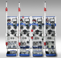
ÄKTAxpress Twin, two module system
ÄKTAexpress has been discontinued. Service of ÄKTAxpress is available until 31 December 2023. After this date, we offer service upon availability of parts from our suppliers.
FAQ
Why should I have REGULAR, PLANNED MAINTENANCE on my system?
With the pressure on producing sample or results, the condition of your ÄKTAdesign or Ettan system is critical and regular servicing will mean you can depend on your system to perform as expected. Planned maintenance can be part of a service agreement, scheduled to service your system before it is in need of attention. We can help you design a schedule and routine to allow you to maintain your system, please contact your local Cytiva service representative.
So what can you expect from a planned maintenance visit from Cytiva service representative?
- Thorough inspection and cleaning of system components
- Update of system firmware to ensure full compatibility of your system and UNICORN software
- Replacement of damaged or corroded seals, valve springs and solenoids
- Replacement of items that are reaching the end of their expected life – preventing future breakdowns
- Advice and guidance on proper daily use, cleaning and care of your system
- All work is documented and reported to help make any regulatory audits easier.
A complete overhaul, once a year, ensures that your instrument is running at peak performance so you can be confident of your scientific results. In addition, wear and tear on systems under constant use by multiple end users is minimized, giving the system a longer life and better value for money.
To find out more about service possibilities contact your local Cytiva service representative.
What DOCUMENTS are supplied with my system?
ÄKTAxpress
ÄKTAxpress User Manual
ÄKTAxpress Installation Guide
ÄKTAxpress Safety Handbook
Using UNICORN with Windows XP Service Pack 2
UNICORN User Reference Manual chapter 1-11
UNICORN User Reference Manual chapter 12-15
UNICORN Administration and Technical Manual
System certificate
ÄKTAxpress
Chemical resistance guide
Introduction
This section specifies the chemical resistance of ÄKTAxpress to some of the most commonly used chemicals in liquid chromatography.
Note: ÄKTAxpress is intended to be used with water based solutions only. Organic solvents are not recommended due to the mixer design.
Assumptions made
The ratings are based on the following assumptions:
• The synergy effects of chemical mixtures have not been taken into account.
• Room temperature and limited overpressure is assumed.
Note: Chemical influences are time and pressure dependent. Unless otherwise stated, all concentrations are 100%.
List of chemicals
List of chemicals and their compatibility to ÄKTAxpress:
| Chemical | Exposure < 1day |
Exposure up to 2 months |
Remarks |
| Acetaldehyde | OK | OK | |
| Acetic acid, < 5% | OK | OK | |
| Acetic acid, 70% | OK | OK | |
| Acetonitrile | OK | OK | FFKM, PP and PE swell |
| Acetone, 10% | OK | Avoid | PVDF is affected by long term use |
| Ammonia, 30% | OK | OK | Silicone is affected by long term use |
| Ammonium chloride | OK | OK | |
| Ammonium bicarbonate | OK | OK | |
| Ammonium nitrate | OK | OK | |
| Ammonium sulphate | OK | OK | |
| 1-Butanol | OK | OK | |
| 2-Butanol | OK | OK | |
| Citric acid | OK | OK | |
| Chloroform | OK | Avoid | ECTFE, CTFE, PP and PE are affected by long term use |
| Cyclohexane | OK | OK | |
| Detergents | OK | OK | |
| Dimethyl sulphoxide | Avoid | Avoid | PVDF is affected by long term use |
| 1, 4-Dioxane | Avoid | Avoid | ETFE, PP, PE and PVDF are affected by long term use |
| Ethanol | OK | OK | |
| Ethyl acetate | OK | Avoid | Silicone not resistant Pressure limit for PEEK decreases |
| Ethylene glycol | OK | OK | Silicone not resistant |
| Formic acid | OK | OK | |
| Glycerol | OK | OK | |
| Guanidinium hydrochloride | OK | OK | |
| Hexane | OK | Avoid | Silicone not resistant Pressure limit for PEEK decreases |
| Hydrochloric acid, 0.1 M | OK | OK | Silicone not resistant |
| Hydrochloric acid, > 0.1 M |
OK | Avoid | Silicone not resistant Titanium is affected by long term use |
| Isopropanol | OK | OK | |
| Methanol | OK | OK | |
| Nitric acid, diluted | OK | Silicone not resistant | |
| Nitric acid, 30% | Avoid | Avoid | Elgiloy is affected by long term use |
| Phosphoric acid, 10% | OK | Avoid | Titanium, aluminium oxide and glass are affected by long term use |
| Potassium carbonate | OK | OK | |
| Potassium chloride | OK | OK | |
| Pyridine | Avoid | Avoid | ETFE, PP and PE not resistant |
| Sodium acetate | OK | OK | |
| Sodium bicarbonate | OK | OK | |
| Sodium bisulphate | OK | OK | |
| Sodium borate | OK | OK | |
| Sodium carbonate | OK | OK | |
| Sodium chloride | OK | OK | |
| Sodium hydroxide, 2 M | OK | Avoid | PVDF and borosilicate glass are affected by long term use |
| Sodium sulphate | OK | OK | |
| Sulphuric acid, diluted | OK | Avoid | PEEK and titanium are affected by long term use |
| Sulphuric acid, medium concentration |
Avoid | Avoid | |
| Tetrachloroethylene | Avoid | Avoid | Silicone, PP and PE are not resistant |
| Tetrahydrofuran | Avoid | Avoid | ETFE, CTFE, PP and PE are not resistant |
| Toluene | OK | OK | Pressure limit for PEEK decreases |
| Trichloroacetic acid, 1% | OK | OK | |
| Trifluoroacetic acid, 1% | OK | OK | |
| Urea | OK | OK | |
| o-Xylene p-Xylene |
OK | OK | PP and PE are affected by long term use |
ÄKTAxpress
Cleaning system – Overview
When running different types of samples or purification methods after each other, the sample inlet tubings and the system flow path should be cleaned between the runs. This will prevent buffer mixing, sample contamination and protein precipitation. When leaving the system for the weekend or for a longer time, the cleaning procedure should be finished with 20% ethanol to prevent bacterial growth in the tubing.
Note: Do not leave the system with salt buffer in the flow path. It might damage
the pump.
| WARNING! When using hazardous chemicals, take all suitable protective measures, such as wearing protective glasses and gloves resistant to the chemicals used. Follow local regulations and instructions for safe operation and maintenance of the system. |
| WARNING! When using hazardous chemicals, make sure that the entire system has been flushed thoroughly with bacteriostatic solution, for example, NaOH, and distilled water, before service and maintenance. |
Cleaning sample inlets
It is possible to include cleaning of the sample inlets after sample loading or after the purification run within a Purify method plan.
Cleaning procedures using method plans
There are two types of cleaning procedures available for system cleaning. The table below briefly describes the cleaning procedures.
| Cleaning procedure | Description |
| Standard system cleaning | Automatic cleaning of the system with NaOH, water and affinity/ion exchange buffer. |
| Customized system cleaning |
Automatic cleaning of the system with up to five optional solutions. |
Flushing the tubings manually
The tubings can also be flushed using the following manual instructions (not column or outlet tubings):
• PumpWash
• SystemWash
• LoopWash
These instructions can be executed from the Pump Instructions dialog box by selecting Manual:Pump in SystemControl. The instructions are also included in the method plans where they are automatically executed.
Note: The system is always in Pause mode during PumpWash. Hence, it is only possible to click END or CONTINUE during PumpWash.
For more information about the instructions, click Help in the dialog box.
Standard cleaning of the system
Introduction Standard cleaning of the system includes cleaning of the system with three solutions and can be run:
Included as a post run procedure within a purification method (denoted CIP System) or within the Standard System and Column Procedures prepare and maintain method plan (denoted CIP System and Loops with NaOH-Water-Buffer).
The system will be automatically cleaned, but the sample inlets and the outlets will not be cleaned.
If performing standard cleaning within a Purify method plan, it is possible to include a procedure for cleaning the sample inlets between sample loading or after the run in the purification method (see below).
If performing standard cleaning using the Standard System and Column Procedures prepare and maintain method plan, it is possible to include a procedure for rinsing all outlets (see below).
Note: Do not leave the system with salt buffer in the flow path. It might damage
the pump.
| WARNING! When using hazardous chemicals, take all suitable protective measures, such as wearing protective glasses and gloves resistant to the chemicals used. Follow local regulations and instructions for safe operation and maintenance of the system. |
| WARNING! When using hazardous chemicals, make sure that the entire system has been flushed thoroughly with bacteriostatic solution, for example, NaOH, and distilled water, before service and maintenance. |
Prerequisites
The following are required for automated standard system cleaning:
• Cleaning solutions
The cleaning solutions use dedicated inlet tubings.
• A method plan for cleaning the system
Create a purify method plan including CIP System
The illustration below gives an overview of how to include CIP System in the purification method plan.

Create a Standard System and Column Procedures method plan including
CIP System
The illustration below gives an overview of how to include CIP System and Loops with
NaOH-Water-Buffer in the Standard System and Column Procedures method plan.

Cleaning the system within a purify method plan
Run the purify method plan. CIP System is selected as Post Run and cleaning of the system will be performed after purification.
If cleaning sample inlets, the system will pause and the sample inlet tubings should be moved to a separate flask with the appropriate solution.
Cleaning the system using the Standard System and Column Procedures
method plan
To run the prepare and maintain method plan for cleaning the system:
| Step | Action |
|
1
|
Wash the outside of the inlet tubings with water and/or ethanol. |
|
2
|
If the outlets are to be cleaned, insert a microplate. |
|
3
|
Run the cleaning method plan |
Customized cleaning of the system
Customized cleaning of the system includes cleaning of the system with up to five solutions. It is performed by running the Customized System Procedures prepare and maintain method plan.
The system will be automatically cleaned. It is possible to select to clean the sample inlets, buffer inlets, outlets, column valve and loops in the method plan.
Note: Do not leave the system with salt buffer in the flow path. It might damage
the pump.
| WARNING! When using hazardous chemicals, take all suitable protective measures, such as wearing protective glasses and gloves resistant to the chemicals used. Follow local regulations and instructions for safe operation and maintenance of the system. |
| WARNING! When using hazardous chemicals, make sure that the entire system has been flushed thoroughly with bacteriostatic solution, for example, NaOH, and distilled water, before service and maintenance. |
Prerequisites
The following are required for automated customized system cleaning:
• Cleaning solutions
The operator moves the inlet tubing from solution to solution.
• A Customized System Procedures method plan for cleaning the system, including
selected sample and buffer inlets, loops and outlets.
Create the Customized System Procedures method plan
The illustration below gives an overview of how to create the Customized System
Procedures method plan.

Cleaning the system
To run the method plan for cleaning the system:
| Step | Action |
|
1
|
Wash the outside of the inlet tubings with water and/or ethanol. |
|
2
|
Immerse the ends of the tubings to be used in the container with cleaning solution 1. Note: Inlet tubing A1 is used for all cleaning solutions. The operator moves the inlet tubing from solution to solution. If the system will not be used for a longer time, use a bacteriostatic solution (e.g., 20% ethanol) as the final wash solution. |
|
3
|
If the column valve is to be cleaned, remove the columns and reconnect the tubings to the column block. |
|
4
|
If the outlets are to be cleaned, insert a microplate |
|
5
|
Run the cleaning method plan. |
How can I determine the delay volume?
Three different methods are described below:
Method I - Determining the delay volume of your system by measuring different retention volumes
| 1) Check that the pump is delivering the correct flow at 1 ml/min. If the measured flow rate differs the retention volumes need to be corrected. 2) Mount a small loop, e.g. 100 µl, and prepare a solution of 5% acetone in water to use as sample. 3) Fill the system with clean water. Run manually or make your own method. Start the pump at 1 ml/min and inject the sample. The measured retention volume is called Volume 1. 4) Re-configure your system. Dismount the tubing from the UV flow cell and insert a low dead volume connector, e.g. a female-female Valve connector, in the flow path (replaces the UV flow cell). Mount the “tubing end” of the frac outlet into the UV flow cell and mount a waste-tubing to the bottom of the UV flow cell. 5) Set Frac size to a very large volume, e.g. 100 ml, so that the valve is in the Frac position during the entire run. Start the pump at 1 ml/min and inject the sample. The measured retention volume is called Volume 2. Delay volume = Volume 2 – Volume 1. |
Method II - Determining the delay volume of your system with the help of another ÄKTA system
| This method is more accurate than the one described above, but demands one more system. 1) Check that the pump on your chosen ÄKTA system is delivering the correct flow at 1 ml/min. If the measured flow rate differs the retention volumes need to be corrected. 2) Mount a small loop, e.g. 100 µl, and prepare a solution of 2-5% acetone to use as sample. 3) Fill the system with clean water. Run manually or make your own method. Start the pump at 1 ml/min and inject the sample. The measured retention volume is called Volume 1. 4) Re-configure your system. In e.g. an ÄKTAprime system dismount the tubing from the UV flow cell to the Fraction collector including the restrictor, the Cond cell and the Frac valve. In the other ÄKTA system, e.g. ÄKTApurifier or ÄKTAexplorer, mount the “prime tubing kit” between the tubing to the UV flow cell and the UV flow cell. To do this a low dead volume connector, e.g. a female-female Valve connector, is needed. 5) In order to have the correct flow path the Frac valve in the “prime tubing kit” must be activated. This can be achieved be connecting it to the Valve B port of the P-900 pump in the ÄKTApurifier or ÄKTAexplorer system. The valve is activated by setting Pump B inlet to the B2 position. 6) Start the pump at 1 ml/min and inject the sample. The measured retention volume is called Volume 2. Delay volume = Volume 2 – Volume 1. |
Method III - Determining the delay volume by balancing eluted water
| Manually set the flow path to the direction of the fraction collector. Unscrew the tubing that is connected to inlet of the UV flow cell and insert a luer adaptor instead. Fill a syringe with water and inject water into flow cell unless it drops at the outlet of the fraction collector (in which case you have likely exceeded the pressure in the tubing which might be more than 4 bar, depending on configuration and flow restrictor used). Now fill the syringe with air (at least 20 ml because of compression) and displace the water. Collect eluting water in a small cup. Determine the system delay volume by balancing the cup before and after elution. Repeat two times for calculation of a mean value. Enter the mean value in "system settings" in UNICORN. |
I want to know the DIMENSIONS and WEIGHT of my system.
| System | Height (mm) |
Footprint (mm x mm) |
Weight (kg) |
Flow rate (ml/min) |
Pressure limit (MPa) |
|---|---|---|---|---|---|
| ÄKTA avant 25 | 660 | 860 x 710 | 116 | 0.001-25 | 20 |
| ÄKTA avant 150 | 660 | 860 x 710 | 116 | 0.001-150 (normal range) 0.001-300 (column packing flow) |
5 |
| ÄKTA pure | 630 | 535 x 470 | up to 53 kg | 0.001 to 25 (up to 50 during column packing) |
20 |
| ÄKTA pure 150 | 630 | 535 x 470 | up to 53 kg | 0.01 to 150 (up to 300 during column packing) |
5 |
| ÄKTAexplorer 10 | 620 | 500 x 460 | 75 | 0.001-10 | 25 |
| ÄKTAexplorer 100 | 620 | 500 x 460 | 75 | 0.01-100 | 10 |
| ÄKTAFPLC | 470 | 380 x 480 | 50 | 0.05-20 | 5 |
| ÄKTAmicro | 610 | 480 x 450 | 55 | 0.001-2 | 35 |
| ÄKTApilot | 900 | 750 x 540 | 114 | 4-400 (full gradients) 4-800 (limited gradients) |
2 |
| ÄKTAprime plus | 530 | 400 x 450 | 13 | 0.1-50 | 1 |
| ÄKTApurifier 10 | 620 | 500 x 460 | 75 | 0.001-10 | 25 |
| ÄKTApurifier 100 | 620 | 500 x 460 | 75 | 0.01-100 | 10 |
| ÄKTAxpress | 660 | 490 x 250 | 30 | 0.1-65 | 3 |
| Ettan LC | 610 | 480 x 450 | 55 | 0.001-2 | 35 |
| Ettan MDLC | 710 | 700 x 640 | 105 | 0.001-2 | 35 |
| Ettan microLC | 1150 | 650 x 500 | 77 | 0.001-2 |
35
|
| Ettan nanoLC | 1150 | 650 x 500 | 77 | 0.001-2 | 35 |
I want to know the FLOW and PRESSURE RANGE of my system.
| System | Height (mm) |
Footprint (mm x mm) |
Weight (kg) |
Flow rate (ml/min) |
Pressure limit (MPa) |
|---|---|---|---|---|---|
| ÄKTA avant 25 | 660 | 860 x 710 | 116 | 0.001-25 | 20 |
| ÄKTA avant 150 | 660 | 860 x 710 | 116 | 0.001-150 (normal range) 0.001-300 (column packing flow) |
5 |
| ÄKTA pure | 630 | 535 x 470 | up to 53 kg | 0.001 to 25 (up to 50 during column packing) |
20 |
| ÄKTA pure 150 | 630 | 535 x 470 | up to 53 kg | 0.01 to 25 (up to 300 during column packing) |
5 |
| ÄKTAexplorer 10 | 620 | 500 x 460 | 75 | 0.001-10 | 25 |
| ÄKTAexplorer 100 | 620 | 500 x 460 | 75 | 0.01-100 | 10 |
| ÄKTAFPLC | 470 | 380 x 480 | 50 | 0.05-20 | 5 |
| ÄKTAmicro | 610 | 480 x 450 | 55 | 0.001-2 | 35 |
| ÄKTApilot | 900 | 750 x 540 | 114 | 4-400 (full gradients) 4-800 (limited gradients) |
2 |
| ÄKTAprime plus | 530 | 400 x 450 | 13 | 0.1-50 | 1 |
| ÄKTApurifier 10 | 620 | 500 x 460 | 75 | 0.001-10 | 25 |
| ÄKTApurifier 100 | 620 | 500 x 460 | 75 | 0.01-100 | 10 |
| ÄKTAxpress | 660 | 490 x 250 | 30 | 0.1-65 | 3 |
| Ettan LC | 610 | 480 x 450 | 55 | 0.001-2 | 35 |
| Ettan MDLC | 710 | 700 x 640 | 105 | 0.001-2 | 35 |
| Ettan microLC | 1150 | 650 x 500 | 77 | 0.001-2 |
35
|
| Ettan nanoLC | 1150 | 650 x 500 | 77 | 0.001-2 | 35 |
The performance of all UNICORN controlled ÄKTA systems can be checked by using the installation test that is part of each systems strategy. The installation test checks the function of the liquid delivery and UV monitor systems and can be performed at any time to check the condition of the system.
Correct gradient formation is tested by producing a linear and step gradient of acetone and water. The UV monitoring system is tested by monitoring the absorbance of the acetone at 265, 254 and 280 nm.
Each installation test is designed to be run with the system under pressure as this ensures the efficient opening and closing of the check valves. For systems based on the pumps P-901 and P-903 this pressure is provided by internal restriction in the pumps.
For sanitary systems such as the ÄKTApilot™ the required pressure is provided by the column. Therefore, when performing the ÄKTApilot installation test you must provide pressure to the system, either by using a standard FR-902 flow restrictor or by fitting a length of capillary tubing that gives >0.1 MPa of back pressure.

Spare parts
| # | Product Name | Product Code | Price | |
|---|---|---|---|---|
| 1 | Cable UniNet, L = 0.7 m | 18110974 | 298.00 USD |
Add to cart
|
| 2 | Cable UniNet, L = 1.5 m | 18111775 | 262.00 USD |
Add to cart
|
| 3 | Cable UniNet, L = 3 m | 18110975 | 386.00 USD |
Add to cart
|
| 4 | Cable UniNet L=15 m | 18111774 | 524.00 USD |
Add to cart
|
| 5 | Mains cable 220 V | 19244801 | 110.80 USD |
Add to cart
|
| 6 | Mains cable, 120 V | 19244701 | 71.49 USD |
Add to cart
|
| 8 | Flow Restrictor FR-902 | 18112135 | 758.00 USD |
Add to cart
|
| 9 | Inlet filter holder kit | 11000407 | 167.67 USD |
Add to cart
|
| 10 | Online Filter Holder (classic ÄKTA systems) | 18111244 | 630.00 USD |
Add to cart
|
| 11 | Screw lid kit | 11000410 | 49.68 USD |
Add to cart
|
| 12 | Tube holder | 18117780 | 292.00 USD |
Add to cart
|
| 14 | Large Column Holder, for columns o.d. 50 mm, ÄKTAxpress | 28400737 | 612.00 USD |
Add to cart
|
| 15 | Tubing cutter, for PEEK, EFTE, and FEP tubing i.d. 0.25, 0.5, 0.75, 1 and 1.6 mm | 18111246 | 99.55 USD |
Add to cart
|
| 16 | U-Wrench, M6 | 19748101 | 109.78 USD |
Add to cart
|
| 18 | Fingertight key | 11000356 | 120.06 USD |
Add to cart
|
| 19 | Column Wrap for HiPrep 16 Column | 28902150 | 33.12 USD |
Add to cart
|
| 20 | Flask Holder | 18117779 | 812.00 USD |
Add to cart
|
| # | Product Name | Product Code | Price | |
|---|---|---|---|---|
| 1 | ETFE Tubing, 3 m, i.d.1.0 mm, o.d. 1/16" | 18114238 | 73.48 USD |
Add to cart
|
| 2 | FEP Tubing, 3 m, i.d. 1/16", o.d. 1/8" | 18112116 | 73.48 USD |
Add to cart
|
| 3 | Desalt tubing i.d. 1.0 mm, o.d. 1/16", L=0.35 m | 11000404 | 122.13 USD |
Add to cart
|
Seals are considered as consumables and should be replaced annually or when needed. Please keep a set of each in your stock to prevent long downtime. For code numbers refer to the table below.
| # | Product Name | Product Code | Price | |
|---|---|---|---|---|
| 1 | Piston kit 100 ml | 18111213 | 748.00 USD |
Add to cart
|
| 2 | Pump piston seal kit | 18111204 | 295.00 USD |
Add to cart
|
| 3 | Check valve kit | 18112866 | 1,398.00 USD |
Add to cart
|
| 4 | Flow Restrictor FR-902 | 18112135 | 758.00 USD |
Add to cart
|
| 5 | Hg lamp and housing complete | 28404225 | 2,239.00 USD |
Add to cart
|
| # | Product Name | Product Code | Price | |
|---|---|---|---|---|
| 1 | Fingertight Connector 1/16" Male | 18117263 | 83.91 USD |
Add to cart
|
| 2 | Tubing Connector M6 Male | 18117264 | 51.29 USD |
Add to cart
|
| 3 | Connector for 1/8" tubing | 18112117 | 199.76 USD |
Add to cart
|
| 4 | Union 1/16" Female/M6 Male | 18111257 | 128.73 USD |
Add to cart
|
| 5 | Fingertight Union 1/16" Male/M6 Female | 18111258 | 135.19 USD |
Add to cart
|
| 6 | Union M6 Female - 1/16" Female | 18112394 | 173.88 USD |
Add to cart
|
| 8 | Connector 1/16" Male/Luer Female | 18111251 | 109.24 USD |
Add to cart
|
| 9 | Union 1/16" female-1/16" female | 11000339 | 170.07 USD |
Add to cart
|
| 10 | Ferrule for o.d. 1/8" Tubing | 18112118 | 145.94 USD |
Add to cart
|
| 11 | Fingertight Stop Plug, 1/16'' | 11000355 | 79.16 USD |
Add to cart
|
| 12 | Fingertight connector 1/16" male, narrow | 28401081 | 108.65 USD |
Add to cart
|
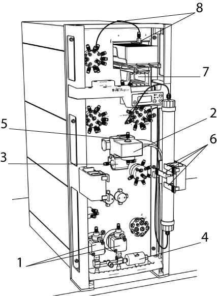
Figure. ÄKTAxpress, front view.
| # | Product Name | Product Code | Price | |
|---|---|---|---|---|
| 1 | Pump piston seal kit | 18111204 | 295.00 USD |
Add to cart
|
| 1 | Piston kit 100 ml | 18111213 | 748.00 USD |
Add to cart
|
| 1 | Check valve kit | 18112866 | 1,398.00 USD |
Add to cart
|
| 2 | Filter 254 nm | 18062001 | 826.00 USD |
Add to cart
|
| 2 | Filter 280 nm | 18062101 | 801.00 USD |
Add to cart
|
| 2 | Hg optics with 254 and 280 nm filters | 28404223 | 7,232.00 USD |
Add to cart
|
| 2 | Hg lamp and housing complete | 28404225 | 2,239.00 USD |
Add to cart
|
| 2 | Hg lamp | 28935493 | 2,215.00 USD |
Add to cart
|
| 3 | Conductivity Flow Cell, 1/16" | 18111105 | 2,352.00 USD |
Add to cart
|
| 3 | Clamp, conductivity cell | 18111114 | 123.72 USD |
Add to cart
|
| 4 | Air sensor, 915 N | 11000308 | 1,196.00 USD |
Add to cart
|
| 6 | Clip for column holder, for columns o.d. 30 mm | 11000292 | 117.99 USD |
Add to cart
|
| 7 | Capillarly loop 10 ml | 11000302 | 364.00 USD |
Add to cart
|
| 8 | Frac nozzle kit | 11002590 | 324.00 USD |
Add to cart
|
| # | Product Name | Product Code | Price | |
|---|---|---|---|---|
| 1 | Fingertight Union 1/16" Male/M6 Female | 18111258 | 135.19 USD |
Add to cart
|
| 2 | Union M6 Female - 1/16" Female | 18112394 | 173.88 USD |
Add to cart
|
| 3 | Connector 1/16" Male/Luer Female | 18111251 | 109.24 USD |
Add to cart
|
| 5 | Tubing Connector M6 Male | 18117264 | 51.29 USD |
Add to cart
|
| 6 | Union 1/16" Female/M6 Male | 18111257 | 128.73 USD |
Add to cart
|
| 7 | Union 1/16" female-1/16" female | 11000339 | 170.07 USD |
Add to cart
|
| 8 | Connector for 1/8" tubing | 18112117 | 199.76 USD |
Add to cart
|
| 9 | Fingertight connector 1/16" male, narrow | 28401081 | 108.65 USD |
Add to cart
|
| 10 | Fingertight Connector 1/16" Male | 18117263 | 83.91 USD |
Add to cart
|
| 11 | Fingertight Stop Plug, 1/16'' | 11000355 | 79.16 USD |
Add to cart
|
| 12 | Ferrule for o.d. 1/8" Tubing | 18112118 | 145.94 USD |
Add to cart
|
| 13 | Online Filter Holder (classic ÄKTA systems) | 18111244 | 630.00 USD |
Add to cart
|
| 14 | U-Wrench, M6 | 19748101 | 109.78 USD |
Add to cart
|
| 15 | Fingertight key | 11000356 | 120.06 USD |
Add to cart
|
| 16 | Tubing cutter, for PEEK, EFTE, and FEP tubing i.d. 0.25, 0.5, 0.75, 1 and 1.6 mm | 18111246 | 99.55 USD |
Add to cart
|
Accessories
Capillary loops and super loops
| # | Product Name | Product Code | Price | |
|---|---|---|---|---|
| 1 | Capillarly loop 10 ml | 11000302 | 364.00 USD |
Add to cart
|
| 2 | Superloop, 1/16" fittings, 10 ml | 18111381 | 1,173.00 USD |
Add to cart
|
| 3 | Superloop, 1/16" fittings (ÄKTAdesign), 50 ml | 18111382 | 1,362.00 USD |
Add to cart
|
| 4 | Loop Extension Kit for ÄKTAxpress | 28904438 | 1,179.00 USD |
Add to cart
|
| # | Product Name | Product Code | Price | |
|---|---|---|---|---|
| 1 | Cable UniNet, L = 0.7 m | 18110974 | 298.00 USD |
Add to cart
|
| 2 | Cable UniNet, L = 1.5 m | 18111775 | 262.00 USD |
Add to cart
|
| 3 | Cable UniNet, L = 3 m | 18110975 | 386.00 USD |
Add to cart
|
| 4 | Cable UniNet L=15 m | 18111774 | 524.00 USD |
Add to cart
|
| 6 | Mains cable, 120 V | 19244701 | 71.49 USD |
Add to cart
|
| 7 | Mains cable 220 V | 19244801 | 110.80 USD |
Add to cart
|
Holders for tube, tubing, column and flask.
| # | Product Name | Product Code | Price | |
|---|---|---|---|---|
| 1 | Tube holder | 18117780 | 292.00 USD |
Add to cart
|
| 3 | Large Column Holder, for columns o.d. 50 mm, ÄKTAxpress | 28400737 | 612.00 USD |
Add to cart
|
| 4 | Column Wrap for HiPrep 16 Column | 28902150 | 33.12 USD |
Add to cart
|
| Flask Holder | 18117779 | 812.00 USD |
Add to cart
|
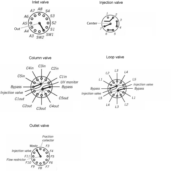
Flow path schemes
For information of each component, place the cursor over the component of interest.
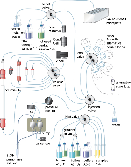
The default position of the valves at start up:
Troubleshooting
Find solutions to product related issues. For unlisted issues please contact local Cytiva service representation.
Error code issues
Issue related to Error code
| Possible cause | Suggested remedy |
|---|---|
Error code flashing on the system |
Check the meaning of the error code in the Error code list, please refer to the ÄKTAxpress User Manual |
High back-pressure
Issues related to High back-pressure
| Possible cause | Suggested remedy |
|---|---|
Affinity chromatography-too small column for the sample volume |
A 5 ml column is recommended for sample volumes more than 20-30 ml. |
Clogged online filter |
Check the online filter, if used. It can become clogged if unfiltered buffers are used |
Dirt or residues in the flow path |
Clean the system using a method plan for system cleaning according to instructions |
Dirty column |
Clean or change column. |
Flow restrictor does not work properly |
Check flow restrictor according to instructions in the ÄKTAxpress User Manual |
Incorrect calibration of pump |
Check the calibration of zero pressure according to instructions in the ÄKTAxpress User Manual |
Sample contain too large particles |
Make sure that the sample has been centrifuges and/or filtered through a 0.45 µm filter, and that no precipitation has occurred prior to sample loading. |
Sample is too viscous |
If using a highly viscous sample, dilute it to ease sample loading. |
Warning "Instruction ignored" is issued during elution
Warning "Instruction ignored" is issued during elution
| Possible cause | Suggested remedy |
|---|---|
Attempt made by the user to execute a manual instruction during the execution of a macro instruction such as PumpWash, SystemWash or LoopWash. |
This will not be allowed. Wait for the macro to finish. |
During a multi step protocol the Peak_InjectSelected instruction does not have any peak to load onto the next column. Peak_InjectSelected instruction will be ignored. |
Check the peak collection parameters User may consider to optimize conditions before next run. |
Eluted peak from step 1 does not meet the peak collection criteria. |
Method will still continue to completion. The user may consider to terminate the run when the message appears. |
Peak fractionation is still active but no additional loops are available. |
No actions are needed, method continues. User may consider to optimize conditions before next run. |
Warning is issued when the maximum number of loops is reached. |
- |
Connection issues
Issues related to Connection
| Possible cause | Suggested remedy |
|---|---|
Power cable is disconnected |
Check that the power cable is connected at the back of the system. If the problem remains, check the log file: c:\unicorn\bin\p4can_drvX.log, where X is the system unit number. |
Power socket has no voltage present. |
Check that the power socket has voltage present. |
| Possible cause | Suggested remedy |
|---|---|
Instrument update has failed |
If the “ÄKTAxpress program update” dialog does not appear in the UNICORN computer, the instrument update failed. |
| Possible cause | Suggested remedy |
|---|---|
Computer is not turned on. |
Check that the computer is turned on. |
Connection status failure, UNICORN Connection status: NO [1] No contact with the systems |
|
Connection status failure, UNICORN Connection status: NO [2] No contact with the ÄKTAxpress driver |
|
Connection status failure, UNICORN Connection status: NO [3] Internal software error (OCI) |
|
Pump showing unusual appearance
Issues related to Pump showing unusual appearance
| Possible cause | Suggested remedy |
|---|---|
Piston seal or rinsing membrane incorrectly fitted or worn |
Replace or re-install the seal or the membrane according to instructions in the ÄKTAxpress User Manual |
| Possible cause | Suggested remedy |
|---|---|
Connector incorrectly fitted or worn |
Unscrew and inspect the connector. If necessary, replace the connector according to instructions in the ÄKTAxpress User Manual |
| Possible cause | Suggested remedy |
|---|---|
Spring is corroded |
Disassemble pump head and examine the piston spring according to instructions in the ÄKTAxpress User Manual. Preventive actions: Make sure the piston rinsing system is always used when working with aqueous buffers with high salt concentration. |
Piston is damaged |
If damaged, replace the piston according to instructions in the ÄKTAxpress User Manual |
Air sensor unusual appearance
Issues related to Air sensor unusual appearance
| Possible cause | Suggested remedy |
|---|---|
Air sensor is not connected |
Check the air sensor cable |
Air sensor is disabled |
Check that the air sensor has not been disabled. Select System:Settings in System Control and then Alarms:Alarm_AirSensor. |
| Possible cause | Suggested remedy |
|---|---|
Sensitivity setting is wrong |
Change to low sensitivity in System:Settings in System Control by selecting Monitors:Airsensor. |
Sample loading issues
Issues related to Sample loading
| Possible cause | Suggested remedy |
|---|---|
Air in tubing |
ÄKTAxpress User Manual Preventive action: Make sure that no air has entered the tubing when moving the tubing from buffer solution to the sample. |
Created air bubbles causing the sample loading to stop due to the air sensor |
Preventive action: Do not place the sample inlet tubing too close to the bottom of the sample tube. |
Connector tighten too hard |
Check the inlet tubing connectors. |
Ferrule distorted |
Check the inlet tubing connectors. Cut the tubing end using a tubing cutter and replace the ferrule. |
Flow restrictor failure |
Check that the flow restrictor generates a back pressure of 0.2 ±0.05 M Pa as follows
|
Sample too viscous |
Dilute the sample to ease sample loading. |
Trapped air bubbles |
Purge the pump to remove trapped air bubbles according to instructions in the ÄKTAxpress User Manual |
Internal leakage
Internal leakage
| Possible cause | Suggested remedy |
|---|---|
Internal fault |
The item must be replaced. |
General advice to achieve good performance
Before using the system make sure that:
- The correct system has been selected in UNICORN System Control
- The correct wavelength has been set for UV/UPC monitor
- All tubing has been properly connected
- All connectors are free from leakage
- No tubing is folded or twisted
- Online filter, if used, is changed on a regular basis
- Correct buffers are used for the chosen columns and proteins
- All inlet tubing has been immersed in correct buffer solutions
- Enough buffer has been prepared
- Buffers have been equilibrated to the environment temperature
- Buffers/eluents have been degassed if necessary (e.g., in RPC runs)
- Suitable columns have been selected for the target proteins
- Columns have been cleaned and prepared according to column instructions
- Samples have been clarified by centrifugation and/or filtration prior to sample loading
- Samples have been adjusted to binding buffer conditions
- Auto sampler (if used) has been prepared according to user manual
- The fraction collector has been filled with appropriate number of microtiter plates or tubes
- Appropriate arrangement for waste handling has been prepared
Conductivity curve
Issues related to Conductivity curve
| Possible cause | Suggested remedy |
|---|---|
Calibration of the conductivity cell is incorrect |
Calibrate the conductivity cell according to instructions in the ÄKTAxpress User Manual |
Calibration solution 1.00 M NaCl not correct prepared |
Prepare a new calibration solution and recalibrate the conductivity cell according to instructions in the ÄKTAxpress User Manual |
| Possible cause | Suggested remedy |
|---|---|
Contaminated conductivity flow cell |
Clean the conductivity cell according to instructions ÄKTAxpress User Manual |
The ambient temperature may have decreased. |
The conductivity of the solution changes with temperature. Since there is no temperature compensation, the measured conductivity will differ at different temperatures. |
The buffer might loose it's characteristics over time |
Change buffer. |
| Possible cause | Suggested remedy |
|---|---|
Air bubbles are passing through the flow cell |
Check for leaking tubing connections and correct according to instructions in the ÄKTAxpress User Manual |
Air might be trapped in the pump |
Purge the pump according to instructions in the ÄKTAxpress User Manual |
| Possible cause | Suggested remedy |
|---|---|
Air might be trapped in the pump |
Purge the pump according to instructions in the ÄKTAxpress User Manual |
Column is not equilibrated |
Equilibrate the column. If necessary, clean the column using a method plan for column cleaning according to instructions in the ÄKTAxpress User Manual |
Conductivity flow cell cable is not correctly connected |
Connect the conductivity cell cable to the rear 1 of the instrument according to the ÄKTAxpress Installation Guide |
| Possible cause | Suggested remedy |
|---|---|
Air in the flow cell |
|
Air might be trapped in the pump |
Purge the pump according to instructions in the ÄKTAxpress User Manual |
Column is not equilibrated |
Equilibrate the column. If necessary, clean the column using a method plan for column cleaning according to instructions in the ÄKTAxpress User Manual |
Contaminated conductivity flow cell |
Clean the conductivity cell according to instructions in the ÄKTAxpress User Manual |
Leaking tubing connections |
Check for leaking tubing connections and correct according to chapter Check the tubing in the ÄKTAxpress User Manual |
| Possible cause | Suggested remedy |
|---|---|
Air might be trapped in the pump |
Purge the pump accordingt to instructions in the ÄKTAxpress User Manual |
Dirt or residues in the flow path from previous run |
Clean the system according to instructions in the ÄKTAxpress User Manual |
Faulty switch valve |
Flush through to clear any blockage by running e.g. system wash accordingt to instructions in the ÄKTAxpress User Manual |
Organic solutions have been used. The mixer is designed for non-organic solution only |
- |
| Possible cause | Suggested remedy |
|---|---|
Air might be trapped in the pump |
Purge the pump according to instructions in the ÄKTAxpress User Manual |
Pressure curve
Issue related to Pressure curve
| Possible cause | Suggested remedy |
|---|---|
Air bubbles passing through or trapped in the pump |
|
Blockage or partial blockage of flow path |
|
Check valves not functioning |
Ther might be dirt in the check valves. Clean the valves according to instructions in the ÄKTAxpress User Manual |
Piston assembly is leaking |
Replace the piston assembly in the pump head according to instructions in the ÄKTAxpress User Manual |
UV curve
Issues related to UV curve
| Possible cause | Suggested remedy |
|---|---|
Air in the eluent or buffers |
Remove the air in the eluent or buffers by degassing. |
Dirt and residues in the flow path from previous run |
Clean the system according to instructions in the ÄKTAxpress User Manual |
| Possible cause | Suggested remedy |
|---|---|
Aging lamp |
Check the lamp running time and replace if necessary according to instructions in the ÄKTAxpress User Manual |
Theoretical extinction coefficient too low |
Calculate the theoretical extinction coefficient of the protein. If it is zero or very low at 280 nm, the protein can not be detected. |
UV lamp in wrong position |
Check that the lamp position and the filter position both are set to the wavelength to be used; 280 nm or 254 nm. Replace the UV lamp according to instructions in the ÄKTAxpress User Manual |
| Possible cause | Suggested remedy |
|---|---|
Air might be trapped in the pump |
Purge the pump using methanol according to the methanol purging procedure in the ÄKTAxpress User Manual |
Air in the flow cell |
|
Contaminated UV-cell |
Clean the UV-cell according to instructions in the ÄKTAxpress User Manual |
Impure buffer |
Check if the signal is still noisy in water. |
Locking nut in the optical unit not properly tightened |
Turn the locking nut to the stop position according to instructions in the ÄKTAxpress User Manual |
Issues when running methods created in the method editor
Issues when running methods created in the method editor
| Possible cause | Suggested remedy |
|---|---|
The default delay volume (0.764 ml) between the UV lamp and the fraction collector has not passed |
Wait until the volume has passed and try again. |
| Possible cause | Suggested remedy |
|---|---|
Delay volume (the LoopParameter instruction volume + 0.44 ml) between the UV lamp and the loop valve has not passed. |
Wait until the volume has passed and try again. |