SOURCE 15Q, 200 mL
Source 15Q is a polymeric, strong anion exchanger designed for polishing steps in both research and industrial applications.
FAQ
Change Control Notifications and Regulatory Support Documentation are available for this product at the Regulatory Support Web Application, www.cytivalifesciences.com/rsf
After registering an account, you can start your subscription free of charge.
Packing procedures
| FineLINE 70 |
|---|
| 2 µm nets |
| Adaptor net Code no: 18-1153-61 |
| End piece net Code no: 18-1153-62 |
| FineLINE 100 |
| 2 µm nets |
| Adaptor net Code no: 11-0034-04 |
| End piece net Code no: 11-0034-05 |
| FineLINE 200 |
| 2 µm nets |
| Adaptor net Code no: 11-0034-06 |
| End piece net Code no: 11-0034-07 |
| FineLINE 350 |
| 2 µm nets |
| Adaptor net Code no: 11-0034-08 |
| End piece net Code no: 11-0034-09 |
| Column | Maximum operation pressure (bar) |
|---|---|
| HiScale | 20 |
| XK 16 | 5 |
| XK 26 | 5 |
| XK 50 | 3 |
| BPG 100 | 8 |
| BPG 140 | 6 |
| BPG 200 | 6 |
| BPG 300 | 4 |
| BPG 450 | 2.5 |
| BioProcess LPLC | 6 |
| BioProcess MPLC | 20 |
| Chromaflow 400 | 3 |
| Chromaflow 600 | 3 |
| Chromaflow 800 | 3 |
| Chromeflow 1000 | 3 |
| FineLINE Pilot 35 | 20 |
| FineLINE 70 | 20 |
| FineLINE 100 | 20 |
| FineLINE 200 | 20 |
| FineLINE 350 | 20 |
| Column | Compression factor | Slurry concentration (%) | Bed height (cm) | Pressure (bar) |
|---|---|---|---|---|
| BioProcess MPLC column 400 | 1.05 | 30 - 50 | 5 - 30 | 3 |
| BioProcess MPLC column 500-800 | 1.05 | 30 - 50 | 10 - 30 | 3 |
| BioProcess MPLC column 900-1200 | 1.05 | 30 - 50 | 15 -30 | 3 |
Recommended flow velocity in the table below is for packing the column.
| Column | Compression factor | Slurry concentration (%) | Bed height (cm) | Flow velocity (ml/min)/ Pressure (bar) |
|---|---|---|---|---|
| FineLINE Pilot 35 | 1.05 | 30 - 50 | 5 - 301 | 100/10 |
1For bed heights above 15 cm run two FineLINE Pilot 35 in series
2 µm stainless steel net
Column evaluation
The efficiency of a column depends on how well it is packed. A poorly packed column gives rise to uneven flow, resulting in zone broadening and reduced resolution. It is thus important to have a method by which the column can be tested before it is put into operation. Such a method should be simple, quantitative and should not introduce contaminating materials. It is also an advantage if the same method can be used to monitor column performance over its working life, so that it is easy to determine when the medium should be re-packed or replaced.
Avoid methods that use colored compounds such as Blue Dextran. They do not meet the above criteria and cannot be used with ion exchange and affinity chromatography media.
Experience has shown that the best method of expressing the efficiency of a column is in terms of the height equivalent to a theoretical plate, HETP, reduced plate number, h, and the peak asymmetry factor, As. These values can be determined easily by applying a NaCl or acetone solution, to the column (see below).
It is important that the column is properly equilibrated ( >2 column volumes) before evaluating the packing. Ideally, run three test runs to see whether the values are stable. If an initially poor result improves during a later test, the reason can be that the column was not properly equilibrated. To check that the bed is stable, run the column at 70% packing pressure for 20 hours and test it again.
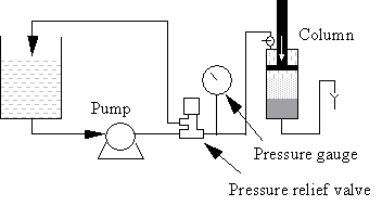
Note that pressure spikes may cause poor packing (cracking). If this happens, fit an air trap and a pressure relief valve between the pump and column. Locate the pressure relief valve between the air trap and the column.
Choice of test sample for columns
The most appropriate material for column testing is, of course, the sample that is to be run in the application, but this is not always practical or economical. As an alternative, a solution of either NaCl or acetone will give a good indication of the column packing quality. The eluate is monitored by measuring conductivity or UV absorption, and the resulting elution profile is used to calculate the HETP value.
The advantages of using NaCl are that it is readily available and can be used safely to test all columns. One disadvantage is that NaCl may interact with the medium matrix, especially ion exchanger matrices, and thus give erroneous results.
Acetone, in contrast, does not interact with the matrix and is detected by UV absorption at 280 nm. Alternatively, you can increase the running buffer concentration 10-fold and use it as test solution.
The figure below shows a UV trace for acetone in a typical BPG column application and gives calculated HETP and As values.

HETP calculation
The sample volume should be approximately 1% of the total bed volume and the concentration 1.0% v/v NaCl, or equivalent when using stronger buffer. Alternatively, use 1.0% v/v acetone. The flow velocity should be between 10 and 30 cm/h depending on the bead size of the chromatography medium. The high flow velocity could be used for small beads whereas large beads only allow low flow velocity. To avoid diluting the sample, apply it as close to the column inlet as possible. If an airtrap is included in the system, by-pass it during sample application to avoid back-mixing. Calculate the HETP value from the conductivity (or UV) curve as follows:
HETP, in its simplest terms, is expressed as:
HETP = L/N
where,
L = Bed height (cm)
N = Number of theoretical plates.
N is defined by the equation:
N = 5.54 (Ve /Wh)2
where,
Ve = Elution volume (ml)
Wh = Peak width at half height (ml)
Ve is measured as the volume passed through the column to the peak maximum.
Wh is measured as the peak width at half-peak height.
From the example in the figure, the HETP value can be calculated from the chromatogram as follows:
| Ve (ml) | Wh (ml) | N | N/m | HETP cm | |
| Acetone | 18800 | 900 | 2417 | 4203 | 0.024 |
Well-packed columns have low HETP values. However, it is only possible to compare columns that have been packed with the same type of media and that have been tested under identical conditions.
As a general rule-of-thumb, a good HETP value is approximately two to four times the mean bead diameter of the medium in question, provided that the sample does not interact with the medium.
In practice, the correlation between HETP and column performance can only be assessed by the column operator. Once this has been established, a standard can be set to judge the acceptability of a column packing.
For example, the column operator may know from experience that a column packed with Sephadex G-25 gel filtration medium with HETP values above 0.05 cm does not give the required separation. Consequently, the operator will set this value as the maximum permissible i.e. the minimum acceptable quality.
Reduced plate number
Definition of reduced plate number: h = HETP/dp
h = reduced plate number.
HETP = above described height equivalent to a theoretical plate.
dp = mean particle diameter of the chromatography medium beads.
The reduced plate number should be in the range of 2-4 times the mean particle diameter of the chromatography medium beads.
Peak asymmetry factor calculation
The peak asymmetry factor should be as close as possible to 1, and the shape of the peak should be as symmetrical as possible. This is usually the case for gel filtration media, but for certain ion exchange and affinity media, the shape may be asymmetrical due to interaction with the media. A change in peak shape is usually the first indication of column deterioration.
The peak asymmetry factor, As, is calculated from the graph above:
As = b/a
where,
a = distance from peak apex to 10% of the peak height on the ascending side of the peak
b = distance from peak apex to 10% of the peak height on the descending part of the peak
Note: Measuring HETP, h and As values is the best way to judge the condition of the packed column. A packed column can look good, but still need repacking for optimal performance. Always check the column after packing and regularly between runs to ensure best performance.
Axial compression packing technique
Single step axial compression packing
1. Flush out air from lower filter by pumping 20% ethanol at 100 ml/min upwards through the filter. Detach the tube to the lower column inlet from the pump and direct the end of the tube to a waste container. Place the tube end higher than the top of the column to avoid draining the column. Suck out excess 20% ethanol from the column tube, leaving approx. 0.5 cm liquid above the filter.
2. Re-suspend the SOURCE medium by shaking (avoid stirring as much as possible). The amount of medium needed is approximately 10% more than the desired volume of the packed bed. Pour approx. 300 ml gel slurry of the desired concentration carefully into the column.
3. Attach the packing pump to the hydraulic inlet with the check valve, with the pressure relief valve (preadjusted to 10 bar) and pressure gauge in line. Put a stop plug in the hydraulic outlet.
4. Pump 20% ethanol through the hydraulic inlet until the ethanol above the slurry is at the level of the inlet.
5. Attach a piece of tubing to the column inlet on top of the adaptor. Insert the adaptor into the column at an angle, ensuring that no air is trapped under the filter. Push the adaptor into the column until both the O-rings on the adaptor are settled in the glass tube. Push down the column lid into the column and lock it. (This will require some force). During this part of the procedure, there will be some flow of 20% ethanol through the tubes at upper and lower column inlets.
6. Put a stop plug in the upper column inlet (on the adaptor). Start the packing pump with a flow rate of 100 ml/min. The pressure should soon rise to 10 bar, as the adaptor moves down and the column packs. The pressure should be held at 10 bar throughout the procedure. Do not change the pump speed during packing
7. When there is no flow from the tube at the lower column inlet, run the pump for another 30 seconds, then stop the pump, disconnect it from the hydraulic inlet and insert a stop plug in the inlet.
8. Start running the column with upward flow.
| FineLINE Pilot 35 |
|---|
| 2 µm nets |
| Adaptor net Code No: 18-1102-10 |
| End piece net Code No: 18-1102-11 |
| Column | Compression factor | Slurry concentration (%) | Bed height (cm) | Pressure (bar) |
|---|---|---|---|---|
| FineLINE 70 | 1.05 | 30 - 50 | 5 - 30 | 6 |
| FineLINE 100 | 1.05 | 30 - 50 | 5 - 30 | 6 |
| FineLINE 200 | 1.05 | 30 - 50 | 5 - 30 | 4 |
| FineLINE 350 | 1.05 | 30 - 50 | 5 - 30 | 4 |
Axial compression packing technique
Refer to the document Axial compression packing, method description and practical example, which you will find under the Related Documents tab.
The pdf. file describes a packing procedure for packing SOURCE 15Q in a FineLINE 100 column using a pressure vessel. The same method is valid for SOURCE 15S, SOURCE 15ETH, SOURCE 15ISO, SOURCE 15PHE, SOURCE 30Q and SOURCE 30S in a FineLINE and BioProcess MPLC columns. The pressure vessel may be replaced with a pump in combination with a pressure relief valve. Using a pressure vessel or pump might be an individual choice or availability of equipment.
Packing buffer: 20 % Ethanol