ÄKTA ready™
ÄKTA ready is a single-use liquid chromatography system built for process scale-up and manufacturing. The systems uses disposable flow paths and prepacked columns that enable flexibility and speed in bioprocessing.
FAQ
If only one of the pumps is running it can be run at full speed. If the pumps are run together the maximum flow rate is still 175 L/h for the Low Flow kit and 510 L/h for the High Flow kit.
The gradient pump is controlled by setting a gradient value (0-100%) and setting a flow rate. A linear gradient is achieved by setting a gradient value and the time/column volume/volume it should take to reach the set gradient value. When the pumps starts they gradually change their output percentage value until the end value is reached.
The Pump tube cannot withstand Gamma irradiation, due to the Polytetrafluoroethylene (PTFE) material. Therefore the pump tube must be autoclaved at a recommended 121°C for 15 min.
The Flow Kit is delivered gamma irradiated or autoclaved. The Flow Kit is intended to be used to process one batch. During operation the Flow Kit can be exposed to 0.5 M NaOH for 2 hours.
Ultrasonic. Two senders and two receivers are measuring the speed difference of the sound in the flow channel against and with the flow. The differences represent the flow in the channel.
Acetone is used to give a UV trace from the UV monitor and Flow cell. It is an easy compound to use and a study has been performed to show how easy it is to rinse out.
EC Declaration of Conformity, Unpacking Instructions, ÄKTA ready Installation Guide, ÄKTA ready Operating Instructions, ÄKTA ready User Manual, ÄKTA ready Safety Instructions, UNICORN User Manual, ÄKTA ready Column Trolly Instructions, ÄKTA design System Log Book.
The pump used with ÄKTA ready systems is of low pulsation due to the use of two double tube elements and a low pulsation pump head with 6 rollers.
In UNICORN we have an installation Wizard that guides you through the installation in a proper way. The Wizard will do an Installation test and will give an acceptance when the monitor readings are correct.
Accessories
1. Assemble the Normal flow filter (NFF) inlet to the flow kit.
2. Evacuate air by filling NFF with liquid. Use the system to pump liquid through the system to the NFF.
3. Assemble the NFF to the column inlet. Extra tubing may be needed to prolong the flow kit. Please make sure the tubing is not folded and does not contain any air.
| # | Product Name | Product Code | Price | |
|---|---|---|---|---|
| TC clamp kit, 25 mm TC | 28404336 | 302.00 USD |
Add to cart
|
|
| TC Clamp kit TC25/SS | 28404338 | 148.09 USD |
Add to cart
|
|
| TC-gasket kit 25 mm i.d. 6.5 mm | 28966737 | 57.00 USD |
Add to cart
|
|
| TC-Gasket 25 mm i.d. 15 mm | 44549288 | 209.00 USD |
Add to cart
|
| Item | Comment |
|---|---|
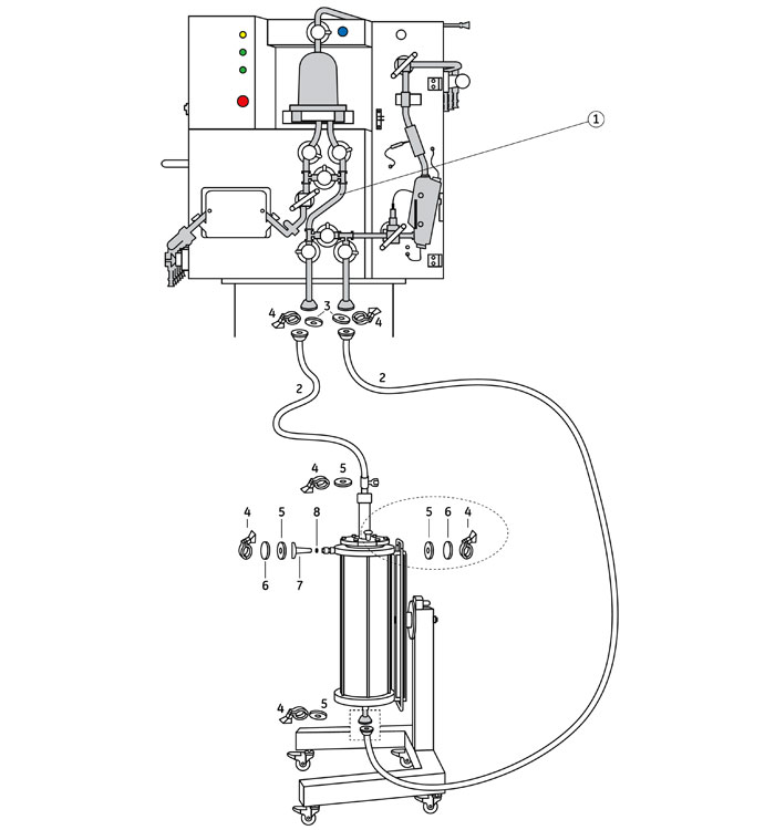
| 1 | Flow kit for flow rates 7.5 l/h-510 l/h, High Flow Kit 28-9301-83. |
| 2 | TC Clamp 25 mm, 28-9381-90 (Stainless steel). 5 clamps are supplied with the column. |
| 3 |
TC Gasket 25 mm i.d. 15.8 mm, 28-9381-88. 5 gaskets supplied with the column. TC Gasket 25 mm i.d. 15 mm, 44-5492-88. 2 gaskets supplied with the flow kit. |
| 4 | For appropriate tubing i.d. refer to table below. |
| 5 | TC Gasket Kit 25 mm, i.d. 9.4 mm, 28-9381-87. |
To isolate the column from the system use Manual Diaphragm Valve, 25 mm TC, i.d. 15,75 mm 28-9382-07 or alternatively only Blind flange 25 mm incl. gasket 18-1001-25 and a TC Clamp 25 mm. Please verify that the pack sizes of clamps and gaskets correspond to your needs.
Column tube and flow kit connections
| Column | Column connection tube material | Column tube i.d. | Flow kit i.d. | TC connection |
|---|---|---|---|---|
| AxiChrom 300 | Stainless steel ASTM 316L | 9.4 mm | 9.4 mm | TC 25 mm |
| AxiChrom 300 | Polypropylene (PP) | 10 mm | 9.4 mm | TC 25 mm |
Tubing
| Tubing i.d. | Code No |
|---|---|
| Tube S-Cor 1/2" (i.d.=12.7), TC25 i.d.= 9.4, 2000 mm | 28-9381-25 |
| Tube S-Cor 1/2" (i.d.=12.7), TC25 i.d.= 9.4, 5000 mm | 28-9381-26 |
| # | Product Name | Product Code | Price | |
|---|---|---|---|---|
| 2 | Clamp, 25 mm TC | 28938190 | 143.86 USD |
Add to cart
|
| 3 | Gasket, 25 mm TC, i.d. 15.8 mm | 28938188 | 289.00 USD |
Add to cart
|
| 3 | TC-Gasket 25 mm i.d. 15 mm | 44549288 | 209.00 USD |
Add to cart
|
| 4 | Tubing, 2 m, i.d. 12.7 mm, 25 mm TC | 28938125 | 2,862.00 USD |
Add to cart
|
| 4 | Tubing, 5 m, i.d. 12.7 mm, 25 mm TC | 28938126 | 4,466.00 USD |
Add to cart
|
| 5 | Gasket, 25 mm TC, i.d. 12.5 mm | 28938187 | 258.00 USD |
Add to cart
|
| Blind Flange, including gasket, 25 mm | 18100125 | 82.80 USD |
Add to cart
|
|
| Manual Diaphragm Valve, 25 mm TC, i.d.15,75 mm | 28938207 | 1,487.00 USD |
Add to cart
|
29032784 Gradient upgrade ÄKTA ready
If you already own an ÄKTA ready system, this kit will allow you to upgrade your ÄKTA ready to enable gradient elution if the system serial number is 1762375 or higher. Please contact your local Cytiva representative to discuss the possibility of upgrading your ÄKTA ready system.
| Item | Comment |
|---|---|
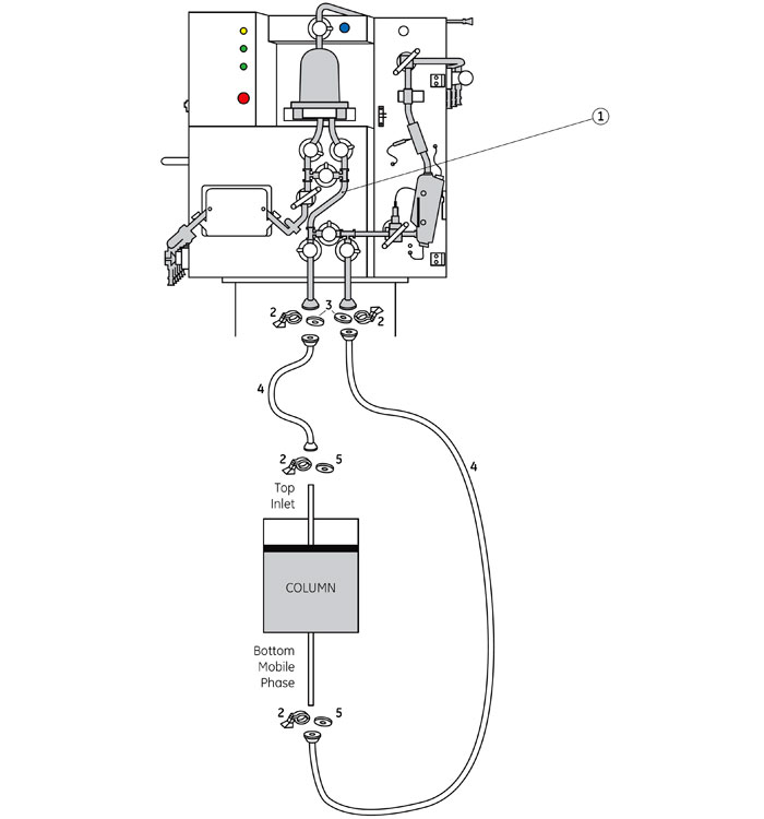
| 1 |
For flow rates 3 l/h-175 l/h use Low Flow Kit 28-9301-82. For flow rates 7.5 l/h-510 l/h use High Flow Kit 28-9301-83. |
| 2 | For appropriate tubing i.d. refer to table below. |
| 3 | TC Gasket 25 mm i.d. 15 mm 44-5492-88, gaskets supplied with the flow kit. Two gaskets i.d. 15 mm needed to connect the column to the flow kit. |
| 4 | TC Clamp 25 mm, 28-4043-38 (Stainless steel) or 28-4043-36 (Polypropylene). Four clamps needed to connect to system. |
| 5 |
TC Gasket Kit 25 mm, i.d. 6.5 mm, 28-9667-37. Two gaskets i.d. 6.5 mm needed to connect the column to the system. |
| 6 | TC End Cap, 25 mm TC, 28-9667-91. |
| 7 | Connector, 25 mm TC - UNF 5/16" Male, short, 18-1170-08. |
| 8 | O-Ring, 3 × 1 mm 18-1169-12. |
To isolate the column from the system use 2-port, 2-way Valve i.d. 6 mm, 44-5501-00 (left) or 44-5501-01 (right) or alternatively only TC End Cap, 25 mm TC, 28-9667-91, TC Clamp 25 mm and a gasket. Please verify that the pack sizes of clamps and gaskets correspond to your needs.
Tubing
| Column | Tubing i.d. | Tubing connection |
|---|---|---|
| AxiChrom 140 | 3.2 mm1 or 4.8 mm2 | 25 mm TC |
| AxiChrom 200 | 6.4 mm | 25 mm TC |
1 It is recommended to use tubing with id 3.2 mm for media with an approximate bead size < 50 µm.
2 For media with an approximate bead size > 50 µm it is recommended to use tubing with id 4.8 mm.
| # | Product Name | Product Code | Price | |
|---|---|---|---|---|
| 3 | TC-Gasket 25 mm i.d. 15 mm | 44549288 | 209.00 USD |
Add to cart
|
| 4 | TC clamp kit, 25 mm TC | 28404336 | 302.00 USD |
Add to cart
|
| 4 | TC Clamp kit TC25/SS | 28404338 | 148.09 USD |
Add to cart
|
| 5 | TC-gasket kit 25 mm i.d. 6.5 mm | 28966737 | 57.00 USD |
Add to cart
|
| 6 | TC end cap | 28966791 | 398.00 USD |
Add to cart
|
| 7 | Connector, 25 mm TC - UNF 5/16" Male, short | 18117008 | 209.00 USD |
Add to cart
|
| 8 | ÄKTApilot O-Ring, 3 × 1 mm | 18116912 | 813.00 USD |
Add to cart
|
| 2 port, 2 way valves i.d. 6 mm (left) | 44550100 | 515.00 USD |
Add to cart
|
|
| 2 port, 2 way valves i.d. 6 mm (right) | 44550101 | 503.00 USD |
Add to cart
|
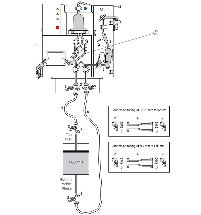
| Item | Comment |
|---|---|
| 1 | Flow kit for flow rates 7.5 l/h-510 l/h, High Flow Kit 28-9301-83. |
| 2 | TC Clamp 25 mm, 28-9381-90 (Stainless steel). 5 clamps are supplied with the column. |
| 3 |
TC Gasket 25 mm i.d. 15.8 mm, 28-9381-88. 5 gaskets supplied with the column. TC Gasket 25 mm i.d. 15 mm, 44-5492-88. 2 gaskets are supplied with the flow kit. |
| 4 | For appropriate tubing i.d., refer to the tables below. |
| 5 | TC Gasket Kit 25 mm, i.d. 9.4 mm, 28-9381-87. |
| 6 | Reducer i.d. 9.4 mm - i.d. 15.75 mm 28-9381-74. 2 reducers are needed to connect column to system. |
To isolate the column from the system use Manual Diaphragm Valve, 25 mm TC, i.d. 15,75 mm 28-9382-07 or alternatively only Blind flange 25 mm incl. gasket 18-1001-25 and a TC Clamp 25 mm. Please verify that the pack sizes of clamps and gaskets correspond to your needs.
Column tube and flow kit connections
| Column | Column connection tube material | Column tube i.d. | Flow kit i.d. | TC connection |
|---|---|---|---|---|
| AxiChrom 400 | Stainless steel ASTM 316L | 15.75 mm | 9.4 mm | TC 25 mm |
| AxiChrom 400 | Polypropylene (PP) | 14.2 mm | 9.4 mm | TC 25 mm |
| AxiChrom 450 | Stainless steel ASTM 316L | 15.75 mm | 9.4 mm | TC 25 mm |
| AxiChrom 450 | Polypropylene (PP) | 14.2 mm | 9.4 mm | TC 25 mm |
Tubing
| Tubing | Code No |
|---|---|
| Tube S-Cor 1/2" (i.d.=12,7), TC25 i.d.=9.4, 2000 mm | 28-9381-25 |
| Tube S-Cor 1/2" (i.d.=12,7), TC25 i.d.=9.4, 5000 mm | 28-9381-26 |
| Tube U-Cor 3/4" (i.d.=19,1), TC25 i.d.=15.75, 2000 mm | 28-9381-27 |
| Tube U-Cor 3/4" (i.d.=19,1), TC25 i.d.=15.75, 2000 mm | 28-9381-28 |
| # | Product Name | Product Code | Price | |
|---|---|---|---|---|
| 2 | Clamp, 25 mm TC | 28938190 | 143.86 USD |
Add to cart
|
| 3 | Gasket, 25 mm TC, i.d. 15.8 mm | 28938188 | 289.00 USD |
Add to cart
|
| 3 | TC-Gasket 25 mm i.d. 15 mm | 44549288 | 209.00 USD |
Add to cart
|
| 4 | Tubing, 2 m, i.d. 12.7 mm, 25 mm TC | 28938125 | 2,862.00 USD |
Add to cart
|
| 4 | Tubing, 5 m, i.d. 12.7 mm, 25 mm TC | 28938126 | 4,466.00 USD |
Add to cart
|
| 4 | Tubing, 2 m, i.d. 19.1 mm, 25 mm TC | 28938127 | 3,082.00 USD |
Add to cart
|
| 4 | Tubing, 5 m, i.d. 19.1 mm, 25 mm TC | 28938129 | 6,133.00 USD |
Add to cart
|
| 5 | Gasket, 25 mm TC, i.d. 12.5 mm | 28938187 | 258.00 USD |
Add to cart
|
| 6 | Concentric Reducer, 25 mm TC (i.d. 9.4 mm) to 25 mm TC (i.d. 15.75 mm) | 28938174 | 634.00 USD |
Add to cart
|
| Blind Flange, including gasket, 25 mm | 18100125 | 82.80 USD |
Add to cart
|
|
| Manual Diaphragm Valve, 25 mm TC, i.d.15,75 mm | 28938207 | 1,487.00 USD |
Add to cart
|
| # | Product Name | Product Code | Price | |
|---|---|---|---|---|
| TC Clamp 25mm SS | 18100131 | 47.13 USD |
Add to cart
|
|
| Termination plug | 18111859 | 27.45 USD |
Add to cart
|
|
| Mains cable 220 V | 19244801 | 110.80 USD |
Add to cart
|
|
| Communications cable RJ45-RJ45/IP67, length = 10 m | 28404163 | 261.00 USD |
Add to cart
|
|
| Pneu. air tube o.d. 10 mm, i.d. 8 mm, L=10 m | 28407194 | 213.00 USD |
Add to cart
|
|
| Wheel without brake | 28931366 | 199.62 USD |
Add to cart
|
|
| Castor with brake | 28931377 | 442.00 USD |
Add to cart
|
|
| TC-Clamp 25 mm | 44050805 | 220.00 USD |
Add to cart
|
|
| TC-Gasket 25 mm i.d. 15 mm | 44549288 | 209.00 USD |
Add to cart
|
|
| Door Key, square | 44551050 | 41.95 USD |
Add to cart
|
1. Assemble the Normal flow filter (NFF) inlet to the flow kit.
2. Evacuate air by filling NFF with liquid. Use the system to pump liquid through the system to the NFF.
3. Assemble the NFF to the column inlet. Extra tubing may be needed to prolong the flow kit. Please make sure the tubing is not folded and does not contain any air.
| # | Product Name | Product Code | Price | |
|---|---|---|---|---|
| TC clamp kit, 25 mm TC | 28404336 | 302.00 USD |
Add to cart
|
|
| TC Clamp kit TC25/SS | 28404338 | 148.09 USD |
Add to cart
|
|
| Clamp, 50 mm TC | 28938191 | 265.00 USD |
Add to cart
|
|
| Gasket 51 mm | 28966886 | 91.28 USD |
Add to cart
|
|
| TC-Gasket 25 mm i.d. 15 mm | 44549288 | 209.00 USD |
Add to cart
|
|
| Gasket 50 mm (1.5") TC i.d. 38 mm, silicone | 56410996 | 92.12 USD |
Add to cart
|
To isolate the column from the system use TC End Cap, 25 mm TC incl. gaskets 18-1001-25 and TC Clamp 25 mm.
For flow rates 3 l/h-175 l/h use Low Flow Kit 28-9301-82.
For flow rates 7.5 l/h-510 l/h use High Flow Kit 28-9301-83.
The ReadyToProcess 32 L (450/200) columns have an extra tube connected to the top outlet. This tube should be used to connect the column to the ÄKTA ready System.
| # | Product Name | Product Code | Price | |
|---|---|---|---|---|
| 5 | TC-Gasket 25 mm i.d. 15 mm | 44549288 | 209.00 USD |
Add to cart
|
| 6 | TC clamp kit, 25 mm TC | 28404336 | 302.00 USD |
Add to cart
|
| 7 | Blind Flange, including gasket, 25 mm | 18100125 | 82.80 USD |
Add to cart
|

The upgrade kit contains UNICORN strategy CD for UNICORN 7 that allows the ÄKTA ready systems to be run with UNICORN 7.0.1 or later versions and the ÄKTA ready Operating Instructions. The UNICORN 7 license need to be bought separately.

| Item | Comment |
|---|---|
| 1 |
For flow rates 3 l/h-175 l/h use Low Flow Kit 28-9301-82. For flow rates 7.5 l/h-510 l/h use High Flow Kit 28-9301-83. |
| 2 | For Low Flow Kit use tubing with i.d. 6 mm and for High Flow Kit use tubing with i.d. 9.5 mm (PTFE) or 10 mm (PVC), refer to tables below. |
| 3 | TC Gasket 25 mm i.d. 15 mm 44-5492-88, two gaskets are supplied with the flow kit. Two gaskets i.d. 15 mm are needed to connect column to system. |
| 4 | TC Clamp 25 mm 28-4043-38 (Stainless steel) or 44-4043-36 (Polypropylene). |
| 5 |
For Low Flow Kit use 4-port, 2-way Valve, i.d. 6 mm, 25 mm TC 18-5757-01. For High Flow Kit use 4-port, 2-way Valve i.d. 10 mm, 25 mm TC 18-1012-56. |
| 6 |
For Low Flow Kit use gasket with i.d. 6 mm 18-0019-27 or i.d. 8 mm 28-9509-48. For High Flow Kit use gasket with i.d. 10 mm 18-1035-79. |
To isolate the column from the system use 4-port, 2-way valves or alternatively only TC End Cap, 25 mm TC incl. gaskets 18-1001-25 and TC Clamp 25 mm.
PTFE tubing with 25 mm TC
| Inner Diameter | Length | Code Number |
|---|---|---|
| 6 mm | 0.5 m | 28-4053-68 |
| 6 mm | 0.8 m | 28-4053-69 |
| 6 mm | 1 m | 28-4053-70 |
| 6 mm | 2 m | 28-4053-71 |
| 6 mm | 4 m | 28-4053-72 |
| 9.5 mm | 0.5 m | 28-4053-73 |
| 9.5 mm | 0.8 m | 28-4053-75 |
| 9.5 mm | 1 m | 28-4053-76 |
| 9.5 mm | 2 m | 28-4053-77 |
| 9.5 mm | 4 m | 28-4053-78 |
PVC tubing with 25 mm TC
| Inner Diameter | Length | Code Number |
|---|---|---|
| 6 mm | 0.3 m | 18-0005-42 |
| 6 mm | 0.75 m | 18-0005-43 |
| 6 mm | 1.25 m | 18-0005-44 |
| 6 mm | 1.5 m | 18-0005-45 |
| 6 mm | 2 m | 18-0005-47 |
| 10 mm | 0.3 m | 18-1012-85 |
| 10 mm | 0.4 m | 18-1012-86 |
| 10 mm | 0.9 m | 18-1012-62 |
| 10 mm | 1.4 m | 18-1012-63 |
| 10 mm | 1.7 m | 18-1012-64 |
| 10 mm | 2 m | 18-1012-87 |
| # | Product Name | Product Code | Price | |
|---|---|---|---|---|
| 2 | Tubing, 300 mm, 25 mm TC, i.d. 6 mm | 18000542 | 377.00 USD |
Add to cart
|
| 2 | Tubing, 750 mm, 25 mm TC, i.d. 6 mm | 18000543 | 403.00 USD |
Add to cart
|
| 2 | Tubing, 1250 mm, 25 mm TC, i.d. 6 mm | 18000544 | 409.00 USD |
Add to cart
|
| 2 | Tubing, 1500 mm, 25 mm TC, i.d. 6 mm | 18000545 | 423.00 USD |
Add to cart
|
| 2 | Tubing, 2000 mm, 25 mm TC, i.d. 6 mm | 18000547 | 474.00 USD |
Add to cart
|
| 2 | Tubing, 900 mm, 25 mm TC, i.d.10 mm | 18101262 | 393.00 USD |
Add to cart
|
| 2 | Tubing, 1400 mm, 25 mm TC, i.d.10 mm | 18101263 | 413.00 USD |
Add to cart
|
| 2 | Tubing, 1700 mm, 25 mm TC, i.d. 10 mm | 18101264 | 441.00 USD |
Add to cart
|
| 2 | Tubing, 300 mm, 25 mm TC, i.d. 10 mm | 18101285 | 372.00 USD |
Add to cart
|
| 2 | Tubing, 400 mm, 25 mm TC i.d. 10 mm | 18101286 | 381.00 USD |
Add to cart
|
| 2 | Tubing, 2000 mm, 25 mm TC, i.d. 10 mm | 18101287 | 507.00 USD |
Add to cart
|
| 2 | Tubing with Sanitary Fittings, 50 cm, i.d. 6 mm, 25 mm TC | 28405368 | 506.00 USD |
Add to cart
|
| 2 | Tubing with Sanitary Fittings, 80 cm, i.d. 6 mm, 25 mm TC | 28405369 | 531.00 USD |
Add to cart
|
| 2 | Tubing with Sanitary Fittings, 1 m, i.d. 6 mm, 25 mm TC | 28405370 | 535.00 USD |
Add to cart
|
| 2 | Tubing with Sanitary Fittings, 2 m, i.d. 6 mm, 25 mm TC | 28405371 | 681.00 USD |
Add to cart
|
| 2 | Tubing with Sanitary Fittings, 4 m, i.d. 6 mm, 25 mm TC | 28405372 | 827.00 USD |
Add to cart
|
| 2 | Tubing with Sanitary Fittings, 50 cm, i.d. 9.5 mm, 25 mm TC | 28405373 | 514.00 USD |
Add to cart
|
| 2 | Tubing with Sanitary Fittings, 80 cm, i.d. 9.5 mm, 25 mm TC | 28405375 | 573.00 USD |
Add to cart
|
| 2 | Tubing with Sanitary Fittings, 1 m, i.d. 9.5 mm, 25 mm TC | 28405376 | 578.00 USD |
Add to cart
|
| 2 | Tubing with Sanitary Fittings, 2 m, i.d. 9.5 mm, 25 mm TC | 28405377 | 774.00 USD |
Add to cart
|
| 2 | Tubing with Sanitary Fittings, 4 m, i.d. 9.5 mm, 25 mm TC | 28405378 | 1,018.00 USD |
Add to cart
|
| 3 | TC-Gasket 25 mm i.d. 15 mm | 44549288 | 209.00 USD |
Add to cart
|
| 4 | TC clamp kit, 25 mm TC | 28404336 | 302.00 USD |
Add to cart
|
| 4 | TC Clamp kit TC25/SS | 28404338 | 148.09 USD |
Add to cart
|
| 5 | Valve 4-port, 2-way ID 10 | 18101256 | 2,125.00 USD |
Add to cart
|
| 5 | Valve 4-Port 2-Way ID 6 mm | 18575701 | 2,084.00 USD |
Add to cart
|
| 6 | Gasket 25 mm, i.d. 6 mm | 18001927 | 18.97 USD |
Add to cart
|
| 6 | TC-Gasket 25 mm i.d. 10 mm | 18103579 | 34.15 USD |
Add to cart
|
| 6 | TC-gasket 25/8 EPDM | 28950948 | 76.07 USD |
Add to cart
|
| Blind Flange, including gasket, 25 mm | 18100125 | 82.80 USD |
Add to cart
|
| # | Product Name | Product Code | Price | |
|---|---|---|---|---|
| 2 | pH electrode for ÄKTApilot and ÄKTA ready™ | 29386679 | 782.00 USD |
Add to cart
|
| 3 | ÄKTApilot Air Inlet Filter | 18116958 | 184.65 USD |
Add to cart
|
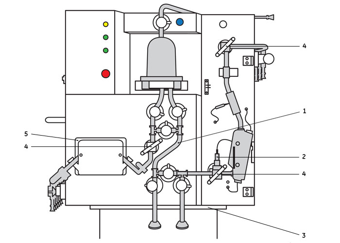
| 4 | Pressure Cell Holder Kit | 28929887 | 511.00 USD |
Add to cart
|
| 5 | Pump Track Assembly | 28930915 | 1,723.00 USD |
Add to cart
|
| ÄKTA ready Air Sensor | 29003879 | 2,563.00 USD |
Add to cart
|
| Item | Comment |
|---|---|
| 1 |
Low Flow Kit, 28-9301-82 (for flow rates 3 l/h-175 l/h). |
| 2 | Connector 25 mm TC- 5/16" female 18-1169-22. Two connectors needed to connect column to system. |
| 3 | TC Gasket 25 mm, i.d. 15 mm 44-5492-88. Two gaskets supplied with the flow kit. Two gaskets i.d. 15 mm needed to connect column to system. |
| 4 | TC Clamp 25 mm, 28-4043-38 (Stainless steel) or 28-4043-36 (Polypropylene). |
| 5 |
For appropriate tubing i.d. refer to table below. |
| 6 | Stop Plug 5/16" male 18-1112-50. |
To isolate the column from the system use Stop Plug 5/16" 28-9819-57.
Tubing
| Column | Tubing i.d. | Tubing connection |
|---|---|---|
| AxiChrom 50 | 1.7 mm | 5/16" |
| AxiChrom 70/100 | 2.9 mm | 5/16" |
| # | Product Name | Product Code | Price | |
|---|---|---|---|---|
| 2 | Connector, 25 mm TC - UNF 5/16" Female | 18116922 | 191.48 USD |
Add to cart
|
| 3 | TC-Gasket 25 mm i.d. 15 mm | 44549288 | 209.00 USD |
Add to cart
|
| 4 | TC clamp kit, 25 mm TC | 28404336 | 302.00 USD |
Add to cart
|
| 4 | TC Clamp kit TC25/SS | 28404338 | 148.09 USD |
Add to cart
|
| 6 | Stop Plug 5/16" Male | 18111250 | 36.22 USD |
Add to cart
|
| Stop plug 5/16" | 28981957 | 98.28 USD |
Add to cart
|
Flow path schemes
The liquid flow through ÄKTA ready is illustrated in the chart below.
(Black: standard components; Red: optional components)
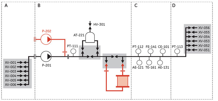
The table below specifies the maximum operating pressure the flow path could be pressurized to with the pressure upgrade strategy in the different parts of the system.
| Part | Description | Pressure |
|---|---|---|
| A | Low pressure, over the Inlet Manifold | 0.6 bar |
| B | High pressure, over the air trap manifold and column | 5.0 bar |
| C | Medium pressure | 2.0 bar |
| D | Medium pressure, over the outlet manifold | 0.95 bar |
The table below describes the system components shown in the flow chart.
| ID tag | Function |
|---|---|
| XV-001 to XV-006 | Inlet 1 to 6, grouped in Inlet Manifold |
| XV-051 to XV-056 | Outlet 1 to 6, grouped in Outlet Manifold |
| PT-111 to PT-113 | 3 Pressure sensor cells |
| AE-121 | pH electrode (optional) |
| FE-141 | Flow meter cell |
| TE-161 | Temperature sensor |
| CE-101 | Conductivity sensor |
| AE-131 | UV cell |
| AT-221 | Air trap |
| HV-301 | Air trap vent valve |
| P-201 | System pump |
| P-202 | Gradient pump (optional) |
From inlet to column
| Stage | Description |
|---|---|
| 1 | Inlet valves open the appropriate inlet (XV-001 to XV-006 in chart) for sample or buffer. |
| 2 | The system pump (P-201) and the gradient pump (P-202) deliver the liquid to the column via a pressure sensor cell (PT-111) and, if preferred, via the air trap (AT-221), where air in the liquid is removed. |
| 3 |
There are two sets of valves between the pump and the column:
|
From column to outlet
| Stage | Description |
|---|---|
| 1 | Downstream of the column, the liquid passes through a second pressure sensor cell (PT-112), which has an integrated flow cell for a pH electrode (AE-121). |
| 2 |
The liquid then continues through:
|
| 3 | The last sensor in the path is a third pressure sensor (PT-113). |
| 4 | Downstream from the sensors, the liquid continues via the outlet tubing to the outlet manifold, where valves (XV-051 to XV-056) divert the liquid to either waste or fraction collection. |
Maximum pressures
- At the outlet manifold, the system works under a pressure of max 0.95 bar.
- Between pump and column the pressure is max 5 bar.
- Between column and outlet manifold the pressure is max 2 bar.
- The different pressure zones are monitored by pressure sensors PT-111 to PT-113.
Consumables
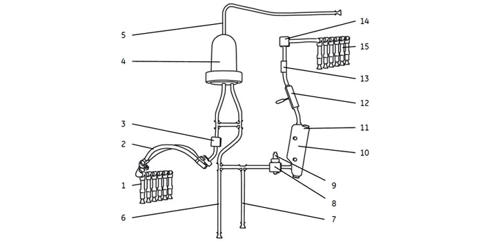
Components of an ÄKTA ready flow kit.
| Part number | Description |
|---|---|
| 1 | Inlet manifold |
| 2 | Pump tubing |
| 3 | Flow cell for pressure sensor |
| 4 | Air trap |
| 5 | Air vent tubing |
| 6 | Column inlet connection |
| 7 | Column outlet connection |
| 8 | Flow cell for pressure sensor |
| 9 | pH electrode (optional) and has to be ordered separately. |
| 10 | Flow meter cell |
| 11 | Temperature cell |
| 12 | Conductivity cell |
| 13 | UV flow cell |
| 14 | Flow cell for pressure sensor |
| 15 | Outlet manifold |
Troubleshooting
Find solutions to product related issues. For unlisted issues please contact local Cytiva service representation.
Pressure sensors
| Possible cause | Suggested remedy |
|---|---|
Incorrect mounting. |
Make sure that each flow cell is properly aligned with its adapter. Check that there is no gap between flow cell and adapter. If necessary, loosen the screws and remount the cell according to the instructions "Mount the main part tubing". The screws holding the latch pressing the flow cell against the adapter should be firmly tightened (using finger force). |
Valves
Issues related to Valves.
| Possible cause | Suggested remedy |
|---|---|
Valve safety lock not closed. |
To close an open valve safety lock: closed. Note: FLOW KIT INSTALL may fill all parts of the flow kit with fluid from the air trap, also inlet and outlets that are currently not used. To avoid spillage of liquid, do not remove the end caps from connections that are not used. |
Tubing not properly inserted. |
If part of the tubing has not been properly inserted in a valve: |
Conductivity measurement
Issues related to Conductivity measurement
| Possible cause | Suggested remedy |
|---|---|
Poor connection. |
Make sure the conductivity sensor's connector cable is properly connected to the system cabinet . See instructions "Mount the |
Wrong inlets used. |
Check that the wash liquid is connected to inlet 6 and the test liquid to inlet 5. |
Wrong composition of wash liquid and/or test solution. |
Make sure that the liquids used are fresh and correctly prepared. See instructions "Prepare a test". |
| Possible cause | Suggested remedy |
|---|---|
Conductivity is temperature compensated and thus dependent on correct temperature readings. The temperature window is located on the back of the flow meter cell. See instructions "Mount the main part tubing". Possible problems with temperature measurement are: 1. Loose flow meter cell. 2. Dirty or damp temperature window. 3. System temperature not stable with respect to surroundings. |
1. Check that the flow meter cell is properly snapped onto its mounting knobs. See instructions "Mount the main part tubing". A gap between the temperature window and the sensor may cause incorrect measurements. 2. Wipe clean with soft tissue. 3. If room temperature changes or if the system is moved from one room to another, it must be given time to adjust to current room temperature. |
Valves
Issues related to Valves.
| Possible cause | Suggested remedy |
|---|---|
A valve lock may be open. |
Check the valve locks. Close if necessary. |
| Possible cause | Suggested remedy |
|---|---|
Alarm is caused by a compressed air failure |
See issues related to Compressed air. |
Pump
Issues related to the Pump.
| Possible cause | Suggested remedy |
|---|---|
Emergency button has been pressed. |
See instructions "Restart after emergency shut down or power failure" for support. |
Pump lid is not properly attached / secured. |
See instructions for support. |
No inlet or outlet valve open. |
Check method and valves. |
Incorrect method. |
Check by entering Pump:ManFlow > 1%. |
If none of the above. |
Contact Cytiva service personnel. |
| Possible cause | Suggested remedy |
|---|---|
Connected inlet is not used. |
Check that connected inlet is actually used. |
Inlet containers are placed too low relative to the pump. |
Check inlet containers. |
No liquid is supplied to the pump. |
Check inlet containers. |
Flow kit tubing is split or burst. |
Replace flow kit. |
Kinks or blockages in the flow kit. |
Remount or replace flow kit. See instructions for mounting the flow kit. |
Pump rotor slipping on the drive shaft. |
Contact Cytiva service personnel. |
| Possible cause | Suggested remedy |
|---|---|
Liquid is too viscous. |
Check that viscosity of liquid is within specified range, according to instructions. |
Pump speed too slow. |
Increase pump speed. |
| Possible cause | Suggested remedy |
|---|---|
Connected outlet is not used. |
Check that connected outlet is actually used. |
Outlet is plugged. |
Check that the outlet is not plugged. |
Too small outlet tubing diameter. |
Change to a larger tubing. |
Flow kit mounted on system for too long, causing the inner walls of the tubing to stick together. |
Replace the flow kit. See instructions for mounting the flow kit. |
Computer
Issues related to the computer.
| Possible cause | Suggested remedy |
|---|---|
Cables are not connected. |
|
System isn't switched on. |
Make sure the system is switched on. |
| Possible cause | Suggested remedy |
|---|---|
Cables are not connected. |
|
System isn't switched on. |
Make sure the system is switched on. |
Power
Issues related to power
| Possible cause | Suggested remedy |
|---|---|
Power failure during a run. |
Check circuit breaker, both in system and for external supply, as applicable. |
Flow meter
Issues related to the Flow meter.
| Possible cause | Suggested remedy |
|---|---|
The lubricant between the flow meter cell and the transducers may be insufficient. |
Lubricate according to the instructions. |
| Possible cause | Suggested remedy |
|---|---|
Transducer surfaces not treated with Vaseline. |
Make sure Vaseline has been applied to the contact surfaces of the transducer connectors. See instructions "Mount the main part tubing". |
Incorrectly mounted pump tubing. |
Check that the pump tubing has been correctly mounted, and that the pump lid is properly secured. Make sure the pegs on the pump lid are turned all the way down. See instructions "Connect and mount the pump tubing". |
Poor pump tubing connection. |
Make sure the TC clamps connecting the pump tubing to the main part of the flow kit, and to the inlet tubing are properly connected and that the TC gaskets are in right position. |
Cavitation (small air bubbles produced by under-pressure), which results in unstable flow meter readings. Cavitation is recognized by a hissing noise. |
- |
UV measurement
Issues related to UV measurement.
| Possible cause | Suggested remedy |
|---|---|
Wrong inlets used. |
Check that the wash liquid is connected to Inlet 6 and the test liquid to Inlet 5. |
Incorrect mounting of UV cell. |
Make sure that the UV cell is pushed all the way in. |
Insufficient light transmission. |
Check that the UV cell and sensor windows are clean and dry. Wipe with soft tissue if necessary. |
Wrong composition of wash liquid and/or test solution. |
Make sure that the liquids used are fresh and correctly prepared. See instructions "Prepare a test". |
Compressed air
Issues related to compressed air.
| Possible cause | Suggested remedy |
|---|---|
Insufficient air pressure caused by, for instance, malfunctioning air supply equipment or a leaking air hose. |
1. Rectify the air supply problem. |
Flow kit
Issues related to the Flow kits.
| Possible cause | Suggested remedy |
|---|---|
Excessive pressure. |
Excessive pressure may damage the flow kit. If excessive pressure is detected and the air trap is in line, press the AIR VENT button on the system cabinet to reduce the pressure. If excessive pressure is detected when the air trap is bypassed, perform the following steps: |
Air in the flow path
Issues related to Air in the flow path.
| Possible cause | Suggested remedy |
|---|---|
Air enters the flow path due to, for instance, damaged tubing or connector, dislocated TC gasket, or inlet hose not properly located in liquid. |
Check for kinks on flow kit tubing. |