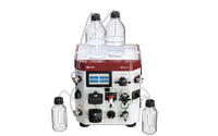
ÄKTA start
ÄKTA start is an easy-to-use chromatography system that automates manual purification procedures using for example HiTrap columns.
FAQ
This chapter provides the necessary instructions to unpack ÄKTA start. Read the entire Installation chapter in ÄKTA start Operating Instructions, before starting to install ÄKTA start.
Note: Save all the original packing material. If the system has to be repacked, for transportation or otherwise, it is important that the system can be safely packed using the original packing material.
Instructions
Follow the instructions to unpack ÄKTA start and Frac30:
Unpack ÄKTA start
| Step | Action |
|---|---|
| 1 | Open the delivery box, take out the document placed at the top of the package and read the Unpacking instructions. |
| 2 | Holding the red strap, lift the instrument out of the delivery box. Place the instrument on the laboratory bench. |
| 3 | Open the strap lock and remove the strap. |
| 4 | Take out the box placed at the top of the package. The box contains the accessories delivered with the instrument. |
| 5 | Remove the foam cushion from the top of the instrument. |
| 6 | Remove the foam cushion from the bottom of the instrument by carefully lifting the instrument. |
| 7 |
Remove the plastic bag by gently tilting the system back and forth while pulling out the plastic bag. Note: The instrument flow path is filled with 50% ethanol at delivery. |
 |
CAUTION Take care not to damage any module or the capillary tubing when lifting the instrument or when removing the plastic bag. |
Unpack Frac30
| Step | Action | ||||
|---|---|---|---|---|---|
| 1 | Open the Frac30 delivery box. | ||||
| 2 | Holding the red strap, lift the fraction collector out of the delivery box. Place the fraction collector on the laboratory bench. | ||||
| 3 | Open the strap lock and remove the strap. Remove the accessories bag located on the foam cushion. | ||||
| 4 | Remove the foam cushion from the top of the fraction collector. | ||||
| 5 | Remove the foam cushion from the bottom of the fraction collector by carefully lifting the fraction collector. | ||||
| 6 | Remove the plastic bag.
|
||||
| 7 |
Remove the Bowl assembly from the Base unit:
|
||||
| 8 | Remove the foam cushion located on the Base unit. | ||||
| 9 |
Re-assemble the Bowl assembly on to the Base unit:
|

Starting the ÄKTA start system, connecting the Frac30 fraction collector and
running a system performance check.
Using predefined methods, Frac30 fraction collector and a gel filtration column to polish proteins.
Using the expanded tools that UNICORN start provides to run the ÄKTA start system from a computer.
Accessories
| # | Product Name | Product Code | Price | |
|---|---|---|---|---|
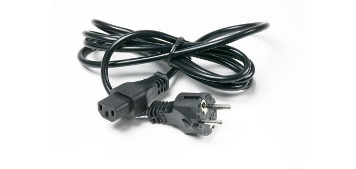
| Mains cable, 120 V | 19244701 | 71.49 USD |
Add to cart
|
|
| Mains cable 220 V | 19244801 | 110.80 USD |
Add to cart
|
|
| USB Cable | 29024036 | 79.69 USD |
Add to cart
|
| # | Product Name | Product Code | Price | |
|---|---|---|---|---|
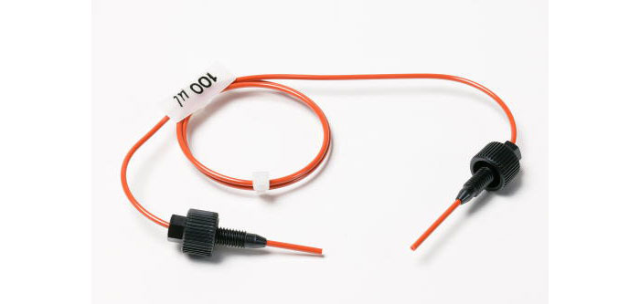
| Sample loop 100 µl | 18111398 | 187.33 USD |
Add to cart
|
|
| Sample loop 500 µl | 18111399 | 243.00 USD |
Add to cart
|
|
| Sample loop 1 ml | 18111401 | 205.00 USD |
Add to cart
|
|
| Sample Loop 2.0 ml | 18111402 | 304.00 USD |
Add to cart
|
|
| Sample loop, 10 µl | 18112039 | 80.73 USD |
Add to cart
|
|
| Sample Loop 5 ml, PEEK | 18114053 | 232.00 USD |
Add to cart
|
|
| Sample loop, FEP 10 ml | 18116124 | 215.00 USD |
Add to cart
|
| # | Product Name | Product Code | Price | |
|---|---|---|---|---|
| Peristaltic pump | 29023992 | 925.00 USD |
Add to cart
|
|
| Pump tubing for ÄKTA start | 29024012 | 425.00 USD |
Add to cart
|

| # | Product Name | Product Code | Price | |
|---|---|---|---|---|
| UV flow cell, 2 mm, for U9-L | 29011325 | 2,835.00 USD |
Add to cart
|
|
| UV Module | 29024018 | 2,563.00 USD |
Add to cart
|
| # | Product Name | Product Code | Price | |
|---|---|---|---|---|
| Screw lid kit | 11000410 | 49.68 USD |
Add to cart
|
|
| Injection Kit, INV-907 | 18111089 | 630.00 USD |
Add to cart
|
|
| Tubing cutter, for PEEK, EFTE, and FEP tubing i.d. 0.25, 0.5, 0.75, 1 and 1.6 mm | 18111246 | 99.55 USD |
Add to cart
|
|
| Inlet Filter Assembly Kit | 18111315 | 190.44 USD |
Add to cart
|
|
| Short column holder, for columns 10 to 50 mm o.d. | 18111317 | 220.00 USD |
Add to cart
|
|
| Inlet Filter Set | 18111442 | 207.00 USD |
Add to cart
|
|
| Column Clamp | 28956319 | 83.84 USD |
Add to cart
|
|
| Accessory Box | 29024037 | 785.00 USD |
Add to cart
|
|
| T-Slot Holders | 29024038 | 95.22 USD |
Add to cart
|
|
| Buffer Tray | 29024039 | 116.95 USD |
Add to cart
|
| # | Product Name | Product Code | Price | |
|---|---|---|---|---|
| PEEK Tubing, 2 m, i.d. 0.75 mm, o.d. 1/16" | 18111253 | 96.26 USD |
Add to cart
|
|
| PEEK Tubing, 2 m, i.d. 0.5 mm, o.d. 1/16" | 18111368 | 73.48 USD |
Add to cart
|
|
| PEEK Tubing, 2 m, i.d. 1.0 mm, o.d. 1/16" | 18111583 | 85.34 USD |
Add to cart
|
|
| Inlet tubing kit for ÄKTA start | 29024032 | 141.79 USD |
Add to cart
|
|
| Replacement tubing kit for ÄKTA start | 29024034 | 357.00 USD |
Add to cart
|
| # | Product Name | Product Code | Price | |
|---|---|---|---|---|
| Manual Injection Valve Kit | 29023917 | 283.00 USD |
Add to cart
|
|
| Manual Injection Valve | 29023958 | 641.00 USD |
Add to cart
|
| # | Product Name | Product Code | Price | |
|---|---|---|---|---|
| Buffer Valve | 29023895 | 501.00 USD |
Add to cart
|
|
| Sample Valve | 29023896 | 569.00 USD |
Add to cart
|
|
| Wash Valve | 29023897 | 501.00 USD |
Add to cart
|
|
| Outlet Valve | 29023898 | 425.00 USD |
Add to cart
|
| # | Product Name | Product Code | Price | |
|---|---|---|---|---|
| Union 1/16" female-1/16" female | 11000339 | 170.07 USD |
Add to cart
|
|
| Stop Plug 5/16" Male | 18111250 | 36.22 USD |
Add to cart
|
|
| Connector 1/16" Male/Luer Female | 18111251 | 109.24 USD |
Add to cart
|
|
| Stop Plug 1/16" Male | 18111252 | 59.00 USD |
Add to cart
|
|
| Fingertight Connector 1/16" Male for Tubing o.d. 1/16" | 18111255 | 123.16 USD |
Add to cart
|
|
| Connector for 1/8" tubing | 18112117 | 199.76 USD |
Add to cart
|
|
| Ferrule for o.d. 1/8" Tubing | 18112118 | 145.94 USD |
Add to cart
|
|
| Fill Port, INV-907 | 18112766 | 266.00 USD |
Add to cart
|
|
| Union 1/16" female-1/16" female | 18385501 | 105.84 USD |
Add to cart
|
| # | Product Name | Product Code | Price | |
|---|---|---|---|---|
| Conductivity Cell | 29024021 | 852.00 USD |
Add to cart
|
| # | Product Name | Product Code | Price | |
|---|---|---|---|---|
| Mixer | 29023960 | 356.00 USD |
Add to cart
|
| # | Product Name | Product Code | Price | |
|---|---|---|---|---|
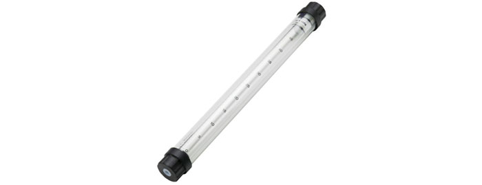
| Superloop Complete, 150 ml, M6 fitting | 18102385 | 1,701.00 USD |
Add to cart
|
|
| Superloop, 1/16" fittings, 10 ml | 18111381 | 1,173.00 USD |
Add to cart
|
|
| Superloop, 1/16" fittings (ÄKTAdesign), 50 ml | 18111382 | 1,362.00 USD |
Add to cart
|
| # | Product Name | Product Code | Price | |
|---|---|---|---|---|
| Tubing Holder | 18646401 | 99.36 USD |
Add to cart
|
|
| Drive sleeve | 19606702 | 133.07 USD |
Add to cart
|
|
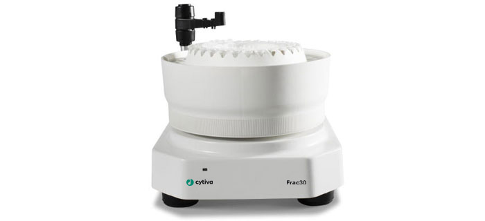
| Frac30 | 29023051 | 2,048.00 USD |
Add to cart
|
|
| Frac30 Bowl Assembly | 29024045 | 142.83 USD |
Add to cart
|
|
| Frac30 Cable Assembly | 29024065 | 425.00 USD |
Add to cart
|

| Tagged package, His Purification of Histidine-tagged proteins HisTrap™ HP (1 × 1 ml) HiTrap™ TALON® crude (1 × 1 ml) HiTrap Desalting (1 × 5 ml) 29-0588-03 |
Tagged package, GST Purification of GST-tagged proteins GSTrap™ 4B (1 × 1 ml) HiTrap Desalting (1 × 5 ml) 29-0588-04 |
| Antibody package, Protein A Purification of human antibodies HiTrap Protein A HP (1 × 1 ml) HiTrap Desalting (1 × 5 ml) 29-0588-05 |
Antibody package, Protein G Purification of most species of antibodies, including rat HiTrap Protein G HP (1 × 1 ml) HiTrap Desalting (1 × 5 ml) 29-0588-06 |
| Untagged package Purification of most proteins, untagged or native HiTrap Q HP (1 × 1 ml) HiTrap SP HP (1 × 1 ml) HiPrep™ 16/60 Sephacryl™ S-200 HR 29-0588-07 |
|
| # | Product Name | Product Code | Price | |
|---|---|---|---|---|
| 1 | Tagged package, His | 29141578 | 168.10 USD |
Add to cart
|
| 2 | Tagged package, GST | 29141636 | 160.92 USD |
Add to cart
|
| 3 | Antibody package, Protein A | 29141638 | 229.60 USD |
Add to cart
|
| 4 | Antibody package, Protein G | 29141639 | 227.55 USD |
Add to cart
|
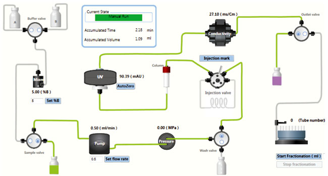
Flow path schemes
The active flow path is depicted in Green color.
A. Flow path details for flow of 100% buffer A through Outlet valve to waste
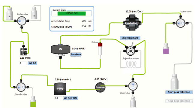
B. Flow path details for flow of 100% buffer B through Outlet valve to waste

C. Flow path details during gradient operation at specified B concentration
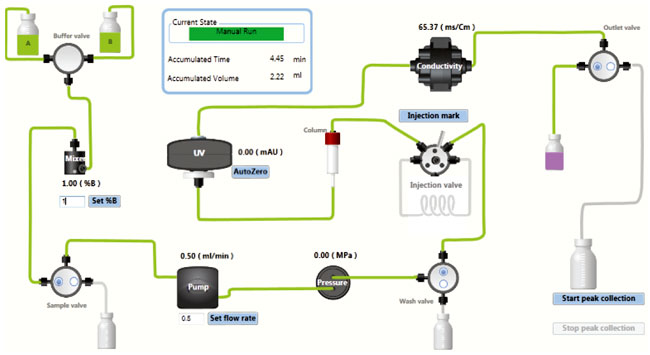
D. Flow path details, Outlet valve collection
Note: Fraction collector is disabled.
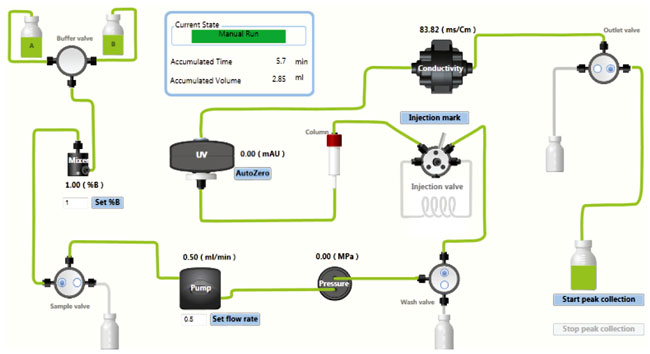
E. Flow path details, fraction collection
Note: Fraction collector is enabled.
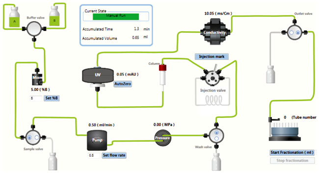
F. Flow path details while loading Sample through the Pump
Spare parts
| # | Product Name | Product Code | Price | |
|---|---|---|---|---|
| Packaging Kit for ÄKTA start | 29032087 | 149.33 USD |
Add to cart
|
|
| Packaging Kit for Frac30 | 29033703 | 142.47 USD |
Add to cart
|
Troubleshooting
Find solutions to product related issues. For unlisted issues please contact local Cytiva service representation.
Pump
Error messages
| Error code | Description | Possible cause | Action |
|---|---|---|---|
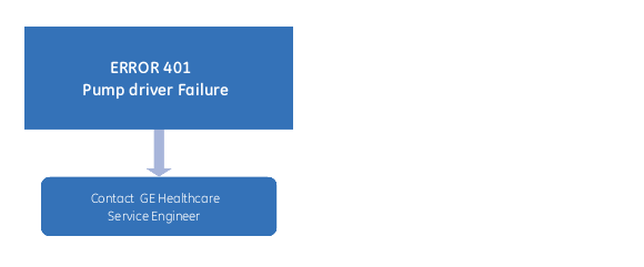
| 401 | Pump failure |
|
|
| - | No flow from the Pump. | The rollers are not rotating, |
|
Pressure sensor
Error messages
| Error code | Description | Possible cause | Action |
|---|---|---|---|
| 501 | Overpressure |
|
|
| 502 | Pressure sensor failure | The sensor is not connected or not calibrated. |
|
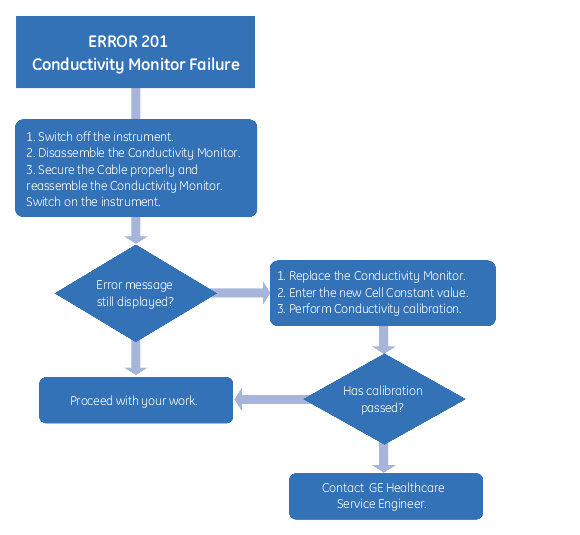
Conductivity
Error messages
| Error code | Description | Possible cause | Action |
|---|---|---|---|
| 201 | Conductivity module failure |
|
See: Troubleshooting Flow chart 6 below. |
System related error messages
Error messages
| Error code | Description | Possible cause | Action |
|---|---|---|---|
| 601 | Method Error. Reload Method |
Incomplete method. Wrong method loaded. |
Reload the method. |
| 602 | Illegal opcode Reload Method |
Incomplete method. Wrong method loaded. |
Reload the method. |
| 603 | Illegal Operation, Restart Instrument | Wrong operations in the system. User is trying to work on features that are not supported. | Restart the system. |
Main board and Power supply
Warning messages
| Warning code | Description | Possible cause | Action |
|---|---|---|---|
| 011 | System over-temperature | The operating temperature is exceeding 35°C (prescribed limit). |
|
Error messages
| Error code | Description | Possible cause | Action |
|---|---|---|---|
| 001 | EPROM error |
|
|
| 002 | MPWA temperature | High temperature inside the system or temperature out of operating range, i.e., > 35°C. |
|
| 003 | Power supply monitor error | Voltage has gone out of operating range. |
|
Troubleshooting flow charts
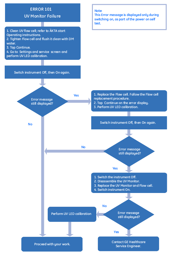
Troubleshooting Flow chart 1
Troubleshooting Flow chart 2
Troubleshooting Flow chart 3
Troubleshooting Flow chart 4
Troubleshooting Flow chart 5
Troubleshooting Flow chart 6
Frac30
Error messages
| Error code | Description | Possible cause | Action |
|---|---|---|---|
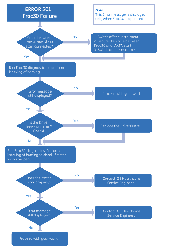
| 301 | Fraction collector failure |
|
See: Troubleshooting Flow chart 4 below. |
UV
Warning messages
| Warning code | Description | Possible cause | Action |
|---|---|---|---|
| 111 | UV intensity low |
In the Settings and service:UV screen: When trying to calibrate; if the detector voltage is less than 2500 mV, even for a max UV light strength of 1024. |
Or,
For instructions, see: UV flow cell and UV LED calibration under Service and settings in the Maintenance manual. |
| 112 | UV intensity high |
In the Settings and service:UV screen: When trying to save the UV light strength after calibration, if the signal is greater than 4000 mV. |
|
| 113 | UV reaching end of lifetime |
In the Settings and service:UV screen: When trying to save the UV light strength after calibration, if the UV light strength is in the range of 1016 to 1020. |
For instructions, see: UV LED calibration and Flow cell path length, in the Maintenance manual. |
| 114 | UV reached end of lifetime |
In the Settings and service:UV screen: When trying to save the UV light strength after calibration, if the UV light strength is 1020. |
For instructions, see: UV LED calibration and Flow cell path length, in the Maintenance manual. |
| 115 | Flush UV flow cell and mount securely |
In the Settings and service:UV screen: When trying to calibrate, if there are repeated calibrations and the signal strength is decreasing. |
|
| 116 | UV baseline ignored |
In the Settings and service:UV screen: Calibration and run time: When the UV signal is not in the range of 2500 mV and 4000 mV, auto zero cannot be performed. |
|
Error messages
| Error code | Description | Possible cause | Action |
|---|---|---|---|
| 101 | UV module failure | During power up, too little light is reaching the detector, i.e., too high absorbance in the cell or to weak light source. | See: Troubleshooting Flow chart 1, below. |
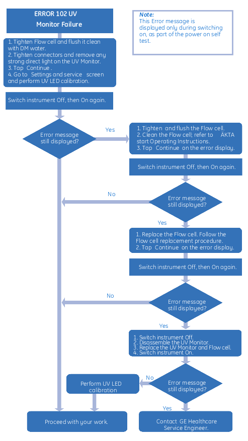
| 102 | UV module failure | During power up, stray light test has failed, light is "leaking" in to the detector. | See: Troubleshooting Flow chart 2, below. |
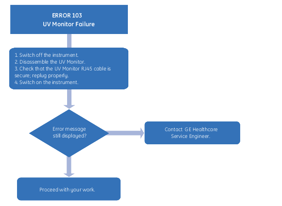
| 103 | UV module failure | UV module cable may be loose or disconnected, no communication with UV module. Main PWA failure. | See: Troubleshooting Flow chart 3, below. |
Maintenance
Maintenance instructions and procedures.
Preventive maintenance
Preventive maintenance should be performed on a daily, weekly and monthly basis. For cleaning instructions, refer to ÄKTA start Operating Instructions.
Maintenance operations should be performed by the user at regular intervals
Visually inspect the instrument for leakages in the flow path.
Check the Pump for leakage. If there are signs of liquid leaking from the Pump, check the integrity of the pump tubing and the tubing connections.
After useClean the column and the system flow path after use and leave the system filled with demineralized water.
Note: If the instrument is not going to be used for a few days, prepare the system for storage.
Visually inspect the inlet filters and clean them if necessary.
(Cleaning procedure: immerse and leave the inlet filters in 1 M NaOH for about 2 hours).
Clean the system flow pathClean the system flow path with 0.5 to 1 M NaOH and rinse with demineralized water.
Note:
- Do not leave the UV flow cell in NaOH for more than 20 minutes.
- Cleaning may be necessary more or less frequently, depending on the system usage and the nature of the samples.
Calibrate the pump
Calibrate the Pump.
Clean the instrument externally.
(Cleaning procedure: wipe the surface with a damp cloth. Wipe off stains using a mild cleaning agent or 20% ethanol.)
Clean the Fraction collectorClean the Fraction collector.
Note: Frac30 is not a spill free design. There will be some spillage when tubes shift position, depending on the flow rate.
Perform System cleaning- Perform System cleaning, Pump wash A and B, Washout fractionation tubing.
- Clean the UV flow cell.
- Clean the Conductivity flow cell.
Calibrate the UV flow cell.
Calibrate the Conductivity flow cellCalibrate the Conductivity flow cell.
Perform Zero offset calibration for the Pressure sensorPerform Zero offset calibration for the Pressure sensor.
Replace the inlet filtersReplace the inlet filters.
Replace the tubing and connectorsReplace the tubing and connectors.
Clean before planned maintenance or service
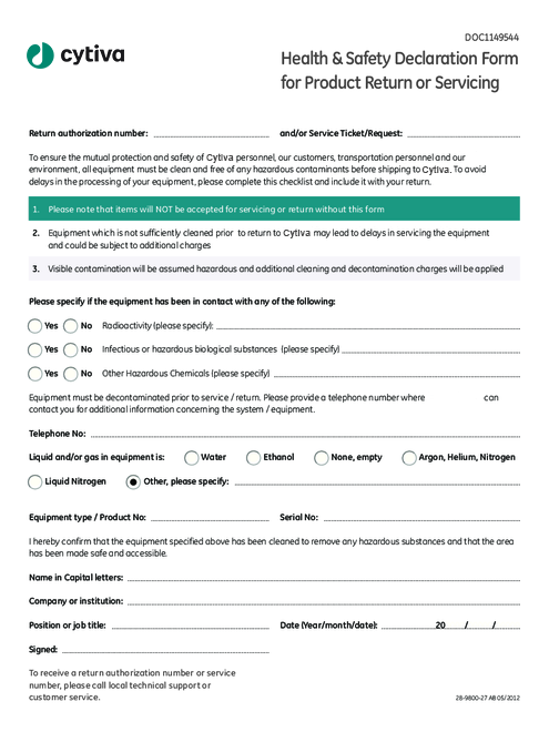
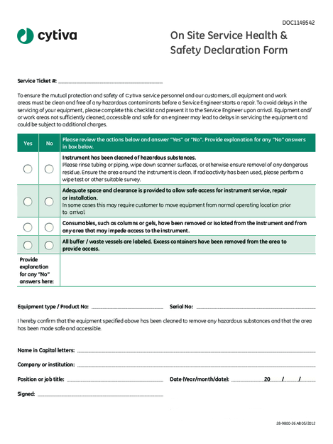
On site service and product return.
Clean before planned maintenance or service
To ensure the protection and safety of service personnel, all equipment and work areas must be clean and free of any hazardous contaminants before a Service Engineer starts maintenance work.
Where it is stated that planned maintenance and/or service of ÄKTA start must be performed by Cytiva service personnel, a Health & Safety Declaration Form must be completed before this is started.
Please complete the checklist in the On Site Service Health & Safety Declaration Form or the Health & Safety Declaration Form for Product Return or Servicing, depending on whether the instrument is going to be serviced on site or returned to Cytiva for service, respectively. Copy the form you need below or print it from the PDF file available on the User Documentation CD.
Access the modules
This section contains maintenance and service instructions for the different modules of the system.
Illustration of the modules and instructions
The illustration below shows the locations of the modules placed on the wet side of the instrument.
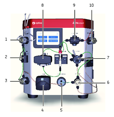
| Part | Module |
|---|---|
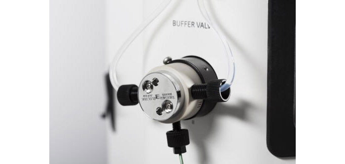
| 1 | Buffer valve |
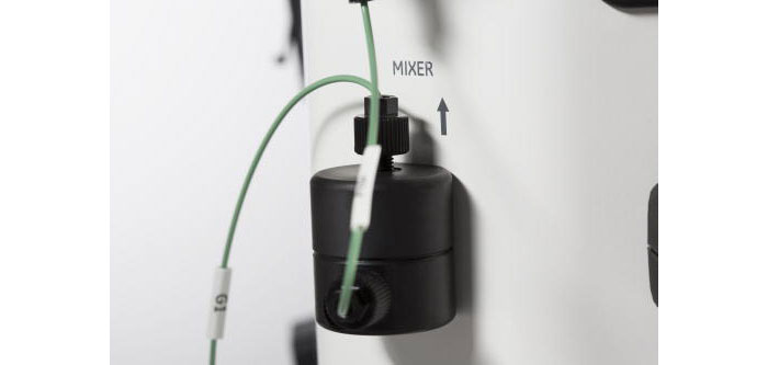
| 2 | Mixer |
| 3 | Sample valve |
| 4 | Pump |
| 5 | Pressure sensor |
| 6 | Wash valve |
| 7 | Injection valve |
| 8 | UV |
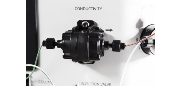
| 9 | Conductivity |
| 10 | Outlet valve |
Instructions
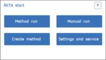
Maintenance and service of the different modules are operated from the Instrument Display. For instructions about maintenance of a module, see the specific sections.
| Step | Action |
|---|---|
| 1 |
Tap Settings and service to access different modules for parameter setting or maintenance. |
| 2 |
Tap Next or Back to move through the screens 1 to 3. Tap the intended module button to select a specific module for maintenance. |
Instructions
Maintenance and service of the different modules are operated from the Instrument Display. For instructions about maintenance of a module, see the specific sections.
| Step | Action |
|---|---|
| 1 |
Tap Settings and service to access different modules for parameter setting or maintenance. |
| 2 |
Tap Next or Back to move through the screens 1 to 3. Tap the intended module button to select a specific module for maintenance. |
UV Monitor
This section describes how to access the UV Monitor options, perform calibrations and edit UV settings.
Access the UV Monitor options
Follow the instructions below to access the options for calibrating and troubleshooting the UV Monitor.
| Step | Action |
|---|---|
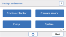
| 1 |
In the Settings and service screen, tap Next:Next to access the 3rd screen. Result: The following screen opens. |
| 2 |
Tap UV to access the UV Monitor options. Result: The UV screen opens. |
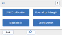
Description
UV LED calibration is used for calibrating the UV LED intensity to get the desired response level of the photo detector.
| Parameter | Description |
|---|---|
| Light | Light intensity needed to get the expected response at the photo detector. |
| T amb | UV temperature sensor reading. |
| Signal | The output of the photo detector at any time (mV). |
Instructions
Follow the instructions below to calibrate the UV LED.
| Step | Action |
|---|---|
| 1 |
Make sure that:
|
| 2 | Flush the UV flow cell with demineralized water using the Pump. Make sure that there are no air bubbles in the UV flow cell. |
| 3 |
Tap UV LED calibration. Result: The following screen opens. 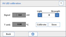 |
| 4 |
Set the Light strength value to 500 using up/down arrows or enter the value. Tap Calibrate. Result: A confirmation screen opens.  |
| 5 |
Tap OK to automatically adjust the Light strength value to get a minimum Signal response of 2500 mV. If the Signal value is above 2500 mV, tap Save. If the Signal value is below 2500 mV use the arrows to increase the Light strength until the Signal is above 2500 mV. |
| 6 |
Tap Save. Result: The calibrated Light strength value is saved and stored in the permanent memory on main board. |
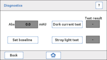
Description
Diagnostics is used to conduct a Dark current test and/or a Stray light test to assess any electrical noise or presence of stray light.
| Test | Description |
|---|---|
| Dark current test |
|
| Stray light test |
Checks the absorbance when the UV flow cell is filled with 15% acetone. Absorbance (Abs) should have a value > 2000 mAU. |
Check for electrical noise
Follow the instructions below to perform a Dark current test.
| Step | Action |
|---|---|
| 1 |
Make sure that:
|
| 2 | Flush and fill the UV flow cell with demineralized water using a syringe. Make sure that there are no air bubbles in the syringe. |
| 3 |
Tap Diagnostics. Result: The Diagnostics screen opens. |
| 4 | Tap Set baseline to capture a new reference value for the test. |
| 5 |
Tap Dark current test. The result is displayed as Pass or Fail:
|
Check for presence of stray light
Follow the instructions below to perform a Stray light test.
| Step | Action |
|---|---|
| 1 | Flush and fill the UV flow cell with 15% acetone using a syringe. Make sure that there are no air bubbles in the syringe. |
| 2 |
Tap Stray light test. The result is displayed as Pass or Fail: Pass: the UV Monitor is working as it should. Fail: clean, reassemble and secure the UV flow cell and the connected tubing. Make sure that the detector is not exposed to e.g., direct sunlight. If the test fails again, replace the flow cell and then possibly the UV Monitor, or contact a Cytiva Service Engineer. |
| 3 | Flush the system with demineralized water so that the Abs value returns close to zero. |
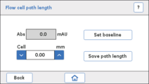
Description
A Flow cell path length test is used to derive the actual path length of the UV flow cell. The test should be performed when the UV Monitor or the UV flow cell has been replaced, and when normalized UV absorption comparisons between different systems are needed.
| Parameter | Description |
|---|---|
| Cell | Path length of the UV flow cell (mm). |
| Abs | The absorbance of the liquid in the UV flow cell (mAU). |
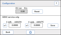
| C amb | Ambient temperature compensation constant. |
| C drft | UV LED drift compensation constant. |
 |
NOTICE UV Configuration of C amb and C drft values must be performed by a Cytiva Service Engineer. The C amb and C drft values should not be altered by a user. |
Prerequisites
- Buffer A: immerse Buffer A inlet into demineralized water.
- Buffer B: freshly prepared 1.0% acetone solution (vol/vol), which is expected to give an absorbance value of 340 mAU.
Instructions
Follow the instructions below to perform a Flow cell path length test and set a new cell length.
| Step | Action |
|---|---|
| 1 | Flush the UV flow cell with demineralized water using the Pump, and then leave the UV flow cell filled with water. |
| 2 |
Tap Flow cell path length. Result: The following screen opens. |
| 3 | Set the Cell value to 2.00 mm by using the up/down arrows or enter the value in the text box. |
| 4 |
Flush the UV flow cell thoroughly and leave it filled with demineralized water. Tap Set baseline to capture a new reference value for the test. Result: Abs should show a value close to 0 mAU. |
| 5 |
Flush the UV flow cell with 1.0% acetone solution, and then leave it filled. Note the new Abs value. |
| 6 |
Calculate the actual Flow cell path length by using the following formula: Cell (mm) = 2.00 * (new Abs value / 340 ) |
| 7 |
Update the calculated Cell length value by using up/down buttons or enter the value. Tap Save path length to save the value to permanent memory. Note: The Abs value should be 340 ± 5% mAU, confirming that normalization has been done. Note: For higher precision, instead of using acetone, use the Fe2(SO4)3 kit, product number: 18-1129-63. |
Instructions
Follow the instructions below to reset the number of run hours of UV Monitor.
|
NOTICE UV Configuration of C amb and C drft values must be performed by a Cytiva Service Engineer. The C amb and C drft values should not be altered by a user. |
Note: After replacing the UV Monitor, it is required to reset the number of run hours of UV Monitor
| Step | Action |
|---|---|
| 1 |
Tap Configuration. Result: The Configuration screen opens. |
| 2 |
Tap Reset. Result: A confirmation screen opens. |
| 3 |
If the UV Monitor has been replaced, tap Yes. Or, If the UV Monitor has not been replaced, tap No to cancel the action. |
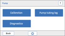
Pump
This section describes how to perform pump diagnostics, calibrations and handle the pump tubing log.
Access the Pump service options
Follow the instruction below to access the options for Pump calibration and troubleshooting.
| Step | Action |
|---|---|
| 1 |
In the Settings and service screen, tap Pump. Result: The Pump screen opens. |
| 2 |
Tap to select the intended option. |
Parameter description
| Parameter | Description |
|---|---|
| Flow rate | Setting of the desired flow rate (ml/min) |
| Pump run | Displays the actual number of run hours for the Pump. |
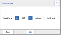
Check the Pump flow rate
Follow the instructions below to perform Pump diagnostics.
| Step | Action |
|---|---|
| 1 | Immerse the buffer inlet tubing A in demineralized water. |
| 2 |
In the Pump screen, tap Diagnostics. Result: The Diagnostics screen opens. |
| 3 |
Use the up/down arrows to set the desired Flow Rate value in the range 0.5 to 5 ml/min. |
| 4 |
Note: Before starting Diagnostics, prime the flow path with water and make sure that the outlet tubing where the pumped water is collected, is filled with demineralized water. This ensures that the volume of the collected water corresponds to the pumped volume. |
| 5 | Collect at least 1 ml of water in the collection tube. Measure and note the collection time. |
| 6 |
Note: If the collected water does not correspond to the required volume (i.e., the Pump does not deliver water with the intended flow rate), inspect the condition of the pump tubing, then re-calibrate the Pump and re-diagnose. If the collected water does not correspond to the required volume replace the Pump tubing. After replacing the pump tubing, calibrate and diagnose the Pump again. If the collected water does not correspond to the required volume replace the Pump. |
| 7 | If the Pump is replaced with a new one, tap Reset to reset Pump run to 0 hours. |
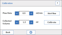
Parameter description
| Parameter | Description |
|---|---|
| Flow rate | The intended flow rate used for Pump calibration. |
| Collected volume | The volume of liquid collected for a certain period of time at the set flow rate. The Collected Volume value and the expected value of the volume corresponding to the set flow rate are used internally for calibration. |
Instructions
Follow the instructions below to calibrate the Pump.
| Step | Action |
|---|---|
| 1 |
Note: Before starting the calibration, prime the flow path with water and make sure that the outlet tubing where the pumped water is collected is filled with demineralized water. This ensures that the volume of the collected water corresponds to the pumped volume. |
| 2 |
In the Pump screen, tap Calibration. Result: The Calibration screen opens. |
| 3 |
Use the up/down arrows to set the desired Flow rate. |
| 4 |
|
| 5 |
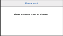
Tap Calibrate. Result: The following screen opens. |
| 6 | Wait while the calibration is running. The calibration is done when the Calibration screen re-opens. |
Parameter description
| Parameter | Description |
|---|---|
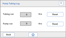
| Tubing run |
Indicates how many hours the pump tubing has been used. When the pump tubing is replaced, use the Reset button to reset the number of hours to 0. |
Instructions
Follow the instructions below to check the Pump tubing log and to reset the number of hours the pump tubing has been used.
| Step | Action |
|---|---|
| 1 |
Tap Pump tubing log. Result: The Pump tubing log screen opens. |
| 2 |
In the Pump tubing log screen, tap Reset. Result: A confirmation screen opens. |
| 3 |
Tap Yes if the pump tubing has been replaced. Or, If the pump tubing has not been replaced, tap No to cancel the action. |

Buffer valve
Description
The Buffer valve can be switched to allow the inlet of either buffer A or buffer B, or a mixture of A and B (gradient).
| Parameter | Description |
|---|---|
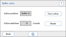
| Valve switches |
Indicates how many times the valve has switched between buffer A or buffer B. When a valve has been replaced, the number of counts has to be reset to 0. Turn valve switches the valve between its two positions, for example the A and B inlet ports. This option is used for troubleshooting the valve. |
Instructions
Follow the instructions below to check if the Buffer valve functions properly.
| Step | Action |
|---|---|
| 1 |
|
| 2 |
Start the Pump: In the Settings and service screen, access Pump:Diagnostics screen. Enter the desired flow rate and then start the Pump by tapping Start flow, and then tap Back:Back to return to the Settings and service screen. |
| 3 |
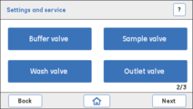
In the Settings and service screen, tap Next to access the 2nd screen. Result: The following screen opens. In the Settings and service screen, tap Buffer valve. Result: The Buffer valve screen opens. |
| 4 |
Check that the valve position Buffer A is selected. Tap Turn valve to check that the Buffer valve switches between Buffer A and Buffer B on the Display. There is also a click sound when the valve switches. Check that the flow is delivered from the Buffer A inlet or the Buffer B inlet, according to the selected valve position. Note: The Buffer valve is by default in the Buffer A position (the liquid is delivered from the Buffer A inlet). |
| 5 |
Visually inspect the flow at the outlet. If the water is not flowing properly, check the following and fix accordingly:
|
| 6 |
Stop the Pump:
|
| 7 | If these checks indicate that the valve is faulty, replace the Buffer valve. |
| 8 |
If the valve has been replaced, tap Reset to set the Valve switches counter to 0. Result: A confirmation screen opens. Tap Yes to confirm the reset if the valve has been replaced. Or, If the valve has not been replaced, tap No to cancel the action. |
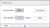
Sample valve
Description
The Sample valve can be switched to allow the inlet of either buffer or sample.
| Parameter | Description |
|---|---|
| Valve switches |
|
Instructions
Follow the instructions below to check if the Sample valve functions properly.
| Step | Action |
|---|---|
| 1 |
|
| 2 |
Start the Pump:
|
| 3 |
In the Settings and service screen, tap Next to access the 2nd screen. Result: The following screen opens. |
| 4 |
In the Settings and service screen, tap Sample valve. Result: The Sample valve screen opens. |
| 5 |
Note: The Sample valve is by default in the Buffer position (the liquid is delivered from the Buffer inlet). |
| 6 |
Visually inspect the flow at the outlet. If the water is not flowing properly, check the following and fix accordingly:
|
| 7 |
Stop the Pump: In the Settings and service screen, access Pump:Diagnostics screen. Stop the Pump by tapping Stop flow. |
| 8 | If these checks indicate that the valve is faulty, replace the Sample valve. |
| 9 |
If the valve has been replaced, tap Reset to set the Valve switches counter to 0. Result: A confirmation screen opens. Tap Yes to confirm the reset if the valve has been replaced. Or, If the valve has not been replaced, tap No to cancel the action. |
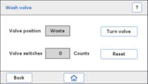
Wash valve
Description
The Wash valve can be switched to divert the flow either to column or to waste.
| Parameter | Description |
|---|---|
| Valve switches |
|
Instructions
Follow the instructions below to check if the Wash valve functions properly.
| Step | Action |
|---|---|
| 1 |
|
| 2 |
Start the Pump: In the Settings and service screen, access Pump:Diagnostics screen. Enter the desired flow rate and then start the Pump by tapping Start flow. |
| 3 |
In the Settings and service screen, tap Next to access the 2nd screen. Result: The following screen opens. In the Settings and service screen, tap Wash valve. Result: The Wash valve screen opens. |
| 4 |
Note: The Wash valve is by default in Waste position (the flow is diverted to waste). |
| 5 |
Visually inspect the flow at the outlet. If the water is not flowing properly, check the following and fix accordingly:
|
| 6 |
Stop the Pump:
|
| 7 | If these checks indicate that the valve is faulty, replace the Wash valve. |
| 8 |
If the valve has been replaced, tap Reset to set the Valve switches counter to 0. Result: A confirmation screen opens. Tap Yes to confirm the reset if the valve has been replaced. Or, If the valve has not been replaced, tap No to cancel the action. |
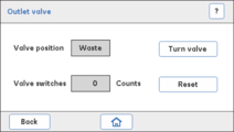
Outlet valve
Description
The Outlet valve can be switched to divert the flow, either to waste or to the Fraction collector.
| Parameter | Description |
|---|---|
| Valve switches |
|
Instructions
Follow the instructions below to check if the Outlet valve functions properly.
| Step | Action |
|---|---|
| 1 |
|
| 2 |
Start the Pump:
|
| 3 |
In the Settings and service screen, tap Next to access the 2nd screen. Result: The following screen opens. In the Settings and service screen, tap Outlet valve. Result: The Outlet valve screen opens. |
| 4 |
Note: The Wash valve is by default in Waste valve position. Hence, the flow is diverted to Waste. |
| 5 |
Visually inspect the flow at the outlet. If the water is not flowing properly, check the following and fix accordingly:
|
| 6 |
Stop the Pump: In the Settings and service screen, access Pump:Diagnostics screen. Stop the Pump by tapping Stop flow. |
| 7 | If these checks indicate that the valve is faulty, replace the Outlet valve. |
| 8 |
If the valve has been replaced, tap Reset to set the Valve switches counter to 0. Result: A confirmation screen opens. Tap Yes to confirm the reset if the valve has been replaced. Or, If the valve has not been replaced, tap No to cancel the action. |
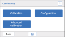
Conductivity monitor
Introduction
This section describes how to perform Conductivity Monitor calibrations and edit the Cell constant settings.
Description
The Conductivity Monitor consists of a conductivity cell with two parallel cylindrical electrodes positioned in the flow path of the cell. One of the electrodes has a temperature sensor for measuring the temperature of the liquid in the cell.
| Parameter | Description |
|---|---|
|
Cell constant (Set cell const) |
The Cell constant is a characteristic of the conductivity cell, defined as the ratio of the distance between the electrodes and the area of an electrode. |
|
Reference temperature (Set ref temp) |
Ambient temperature variations influence the conductivity. In Handbooks and other documentation, the conductivity values are most often given at a certain Reference Temperature (20°C or 25°C). To compare with those values, the actual conductivity has to be re-calculated to conductivity at the reference temperature. |
Instructions
If the flow cell has been replaced, a new cell constant value has to be set. Follow the instructions below to set the Cell constant value.
| Step | Action |
|---|---|
| 1 |
In the Settings and service screen, tap Next:Next to access the 3rd screen. Result: The following screen opens. Tap Conductivity. Result: The Conductivity screen opens. |
| 2 |
Tap Conductivity. Result: The Configuration screen opens. |
| 3 |
Set the Cell constant value (Set cell const) for the new Conductivity flow cell by using the up/down arrows. Tap Save to save the new value. Note:
|
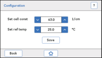
Set the reference temperature
Note: For the system to recalculate the measured conductivity to conductivity at a certain reference temperature, enter the temperature in the Set ref temp field.
Note: Make sure that the checkbox Enable temperature compensation in the Conductivity:Calibration screen is checked.
| Step | Action |
|---|---|
| 1 |
In the Conductivity:Configuration screen, set the reference temperature (Set ref temp) value in the range 4°C to 35°C. |
| 2 | Tap Save to save the new reference temperature. |
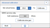
Instructions
Follow the instructions below to calibrate the temperature sensor.
|
NOTICE The option Calibrate sine gen must be performed by Cytiva Service Engineer. |
| Step | Action |
|---|---|
| 1 | Place a precision thermometer in the flow cell path directly after the Conductivity flow cell (i.e., immediately after the conductivity tubing which is connected to Outlet valve), and then pump demineralized water through the system with a flow rate of 0.5 ml/min. |
| 2 |
In the Conductivity screen, tap Advanced calibration. Result: The Advanced calibration screen opens. |
| 3 |
Note the temperature and enter it into the Set actual temp text box, and then tap Calibrate to carry out the temperature calibration Note:
|
Prerequisites
Calibration solution:
- 1.00 M NaCl
or,
- 100 mS/cm conductivity standard solution
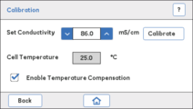
Instructions
Follow the instructions below to calibrate the Conductivity flow cell.
Note: Temperature compensation is enabled by default (factory setting). If you want to disable temperature compensation, tap the Enable temperature compensation checkbox in the Calibration screen.
| Step | Action | ||||||
|---|---|---|---|---|---|---|---|
| 1 | Fill the Conductivity flow cell with conductivity standard solution. | ||||||
| 2 |
In the Conductivity screen, tap Calibration. Result: The Calibration screen opens. Note: Make sure that the checkbox for Enable Temperature Compensation is checked. |
||||||
| 3 | Note the current temperature of the calibration solution in the Conductivity flow cell as displayed in the Cell Temperature field. | ||||||
| 4 |
In the Calibration screen, enter the conductivity value at the current temperature in the Set Conductivity field and then tap Calibrate to carry out the Conductivity calibration. Note:
|

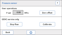
Pressure sensor
Parameter description
| Parameter | Description |
|---|---|
| P set | Displays the current pressure in the flow path (MPa). |
Instructions
Follow the instructions below to set the pressure to 0 when the Pressure sensor is exposed to atmospheric pressure only (Zero offset).
|
NOTICE Calibration of Pressure sensor must be performed by a Cytiva Service Engineer, and must be done when the Pressure sensor has been replaced. |
| Step | Action |
|---|---|
| 1 |
Disconnect the inlet tubing from the Pressure sensor to expose the sensor to atmospheric pressure only. Note: Make sure that the Pump is OFF before disconnecting the tubing. |
| 2 |
In the Settings and service screen, tap Pressure sensor. Result: The Pressure sensor screen opens. |
| 3 |
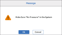
In the Pressure sensor screen, tap Zero offset. Result: A Message screen opens. Make sure that there is no back pressure in the system, and then tap OK. |
Frac30
Instructions
Follow the instructions below to enable or disable Frac30.
| Step | Action |
|---|---|
| 1 |
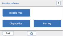
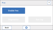
In the Settings and service screen, tap Fraction collector. Result: If the Fraction collector is enabled, the following Fraction collector screen opens. If the Fraction collector is not enabled, the following screen opens. |
| 2 |
Tap Enable Frac to enable the Fraction collector. Or, To disable the Fraction collector, tap Disable Frac. |
Parameter description
| Parameter | Description |
|---|---|
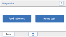
| Feed tube test | Checks that Frac30 rotates the Bowl assembly correctly and shifts one tube at a time. |
| Home test | Checks that Frac30 rotates the Bowl assembly correctly and shifts from the current position to the home position (tube number 1). |
Instructions
Follow the instructions below to run a diagnostics test on Frac30.
| Step | Action |
|---|---|
| 1 |
In the Fraction collector screen, tap Diagnostics. Result: The Diagnostics screen opens. |
| 2 | Tap Feed tube test and visually observe that Frac30 rotates from one tube to the next. |
| 3 |
Tap Home test and visually observe that Frac30 rotates to home position (tube no. 1) from current position. Note: If Frac30 does not rotate the Bowl assembly, check if the Frac30 cable is connected properly to ÄKTA start. If the cable is not connected properly, connect the cable properly and secure it in position with a screw driver if required. |
Parameter description
| Parameter | Description |
|---|---|
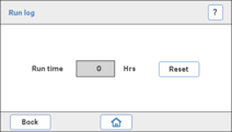
| Run log | Displays the number of hours of drive sleeve usage. |
Instructions
Follow the instructions below to reset the Run log.
| Step | Action |
|---|---|
| 1 |
In the Fraction collector screen, tap Run log. Result: The Run log screen opens. |
| 2 |
If the drive sleeve has been replaced, tap Reset to set the Run time to 0. Result: A confirmation screen opens. Tap Yes to confirm the reset if the drive sleeve has been replaced. Or, If the drive sleeve has not been replaced, tap No to cancel the action. |
Instrument Display
Introduction
This section describes how to calibrate and test the Instrument Display.
Instructions
Follow the instructions below to select an option to calibrate and/or diagnose the Instrument Display.
| Step | Action |
|---|---|
| 1 |
In the Settings and service screen, tap Next:Next to access the 3rd screen. Result: The following screen opens. 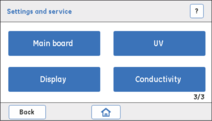 |
| 2 |
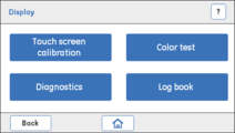
Tap Display to access the Instrument Display options. Result: The Display screen opens. |
Instructions
Follow the instructions below to calibrate the Touch screen.
| Step | Action |
|---|---|
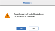
| 1 |
In the Display screen, tap Touch screen calibration. Result: A warning screen opens. |
| 2 |
Tap Yes to proceed with the calibration of the Touch screen. Result: The following screen opens. |
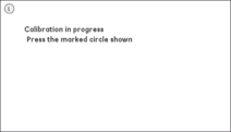
| 3 |
Tap precisely on the marked circle 1. Result: The following screen opens. |
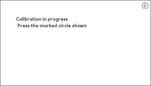
| 4 |
Tap precisely on the marked circle 2. Result: The following screen opens. |
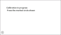
| 5 |
Tap precisely on the marked circle 3. Result: The following screen opens. |
| 6 |
Tap precisely on the marked circle 4. Result: The following screen opens. |
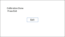
| 7 |
Tap Exit. Note: If the calibration fails, repeat the test. If the calibration fails again, contact a Cytiva Service Engineer. |
Instructions
Follow the instructions below to test the colors of the Touch screen.
| Step | Action |
|---|---|
| 1 |
In the Display screen, tap Color test. Result: The following screen opens. |
| 2 |
Tap Exit. Result: The Color test is completed. Note: If the test fails, contact a Cytiva Service Engineer. |

Instructions
Follow the instructions below to perform diagnostics of the Touch screen.
| Step | Action |
|---|---|
| 1 |
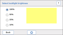
In the Display screen, tap Diagnostics. Result: The following screen opens. |
| 2 |
In the Select backlight brightness screen, tap a radio button to select the intended brightness (%). Result: The rectangle shows the backlight brightness at the selected brightness level. |
| 3 | Tap Back to return to the Display screen. |
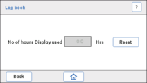
The Log Book displays the number of hours the Instrument Display has been used. If the Instrument Display has been replaced, it is required to reset to 0 the number of hours of display usage.
Note: The instrument display must be replaced by a Cytiva Service Engineer.
Instructions
Follow the instructions below to read the Log book for the Display.
| Step | Action |
|---|---|
| 1 |
In the Display screen, tap Log book. Result: The following screen opens. Note the number of hours the Instrument Display has been used. |
| 2 |
If the Instrument Display has been replaced, tap Reset to set the number of hours to 0. Result: A confirmation screen opens. Tap Yes to confirm the reset if the Instrument Display has been replaced. Or, If the Instrument Display has not been replaced, tap No to cancel the action. |

System
This section describes how to handle firmware updates and export system reports. It also describes how to set delay volumes and switch valve timing.
Parameter descriptions
| Parameter | Description |
|---|---|
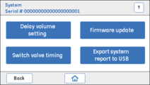
| Delay volume setting | The delay volume represents the volume of liquid found in the flow path between the outlet of the UV Monitor and the collection tubes. This option is used to set the delay volume (ml). |
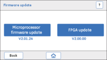
| Firmware update | This option is used to update the firmware version of the instrument whenever a new firmware is available on the ÄKTA start product support page, refer to www.cytivalifesciences.com/AKTA. |
| FPGA update | ÄKTA start has a dedicated digital drive mechanism to improve the life of modules. This is controlled by a digital logic and the firmware can be updated in the field by selecting FPGA update. The required updating files can be downloaded from the ÄKTA start product support page, refer to www.cytivalifesciences.com/AKTA. |
| Switch valve timing |
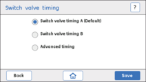
Used for optimizing the switch valve timing. It is recommended to optimize the timing of switch valve (Buffer valve) when wavy gradients are obtained or when fluctuations in the step gradient are observed during either system performance tests or chromatography runs. Available options:
|
| Export system report to USB |
For exporting details on the running condition of the UV, Pump, pump tubing, all the solenoid valves and the latest 4 error messages with Error codes, to a USB memory stick. The latest Firmware version and FPGA version can also be exported. The data is used by a Cytiva Service Engineer when troubleshooting the instrument. |
Instructions
Follow the instructions below to manage the system options.
| Step | Action |
|---|---|
| 1 |
In the Settings and service screen, tap System Result: The following screen opens. |
| 2 | Tap to access a desired system option. |
|
NOTICE Before tapping the Firmware update ensure that the system is connected to a stable source of power such as a UPS. During firmware update the system should not be switched off. |
Prerequisites
- USB memory stick with at least 10 MB free space.
- Delete any previous AKTASTRT.src files located on the USB memory stick.
- Download the latest AKTASTRT.src file from the product support page onto the USB memory stick, refer to (www.cytivalifesciences.com/AKTA).
Instructions
Follow the instructions below to update the firmware.
| Step | Action |
|---|---|
| 1 | Plug the USB memory stick into the USB port located on ÄKTA start. |
| 2 |
In the System screen, tap Firmware update. Result: The following screen opens. |
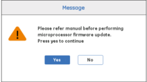
| 3 |
Tap Microprocessor firmware update. Result: The following screen opens. Tap Yes and then wait for approximately 3 minutes for the update to be done. Note: When the firmware update is completed, the instrument automatically restarts and displays the version of the firmware. |
| 4 | From the product support page (www.cytivalifesciences.com/AKTA), download AKTASTRT.dat for FPGA update. |
| 5 |
Tap FPGA update. Result: The following screen opens. 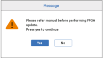 |
| 6 |
Tap Yes. The updating may take up to 5 minutes. Result: The following screen opens. |
| 7 |
Once the firmware is updated, perform the following calibration sequence:
|
Follow the instructions below to export the system report to a USB memory stick. Use the system report in further contacts with Cytiva Service Engineers.
| Step | Action |
|---|---|
| 1 | Plug the USB memory stick into the USB port located on ÄKTA start. |
| 2 |
In the System screen, tap Export System Report to USB. Result: The files INSTLOG.TXT and ERRORLOG.TXT are exported to the USB memory stick. |
| 3 | Remove the USB memory stick from the USB port and connect it to a computer. |
| 4 | Check the content of the system report files INSTLOG.TXT and ERRORLOG.TXT, see section System report file parameters. |
System report files parameters
The content of the INSTLOG.TXT file contains the following parameters:
- ÄKTA start serial no.
- Firmware version
- FPGA version
- Pump run
- Pump tube run
- UV LED run time
- Buffer valve count
- Wash valve count
- Outlet valve count
- Sample valve count
The content of the ERRORLOG.TXT file contains Error codes, for example:
501: Over Pressure
301: Fraction collector failure
603: Illegal operation, restart instrument
Instructions
Follow the instructions below to set the delay volume.
| Step | Action |
|---|---|
| 1 |
In the System screen, tap Delay volume setting. Result: The following screen opens. 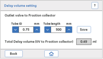 |
| 2 |
Enter the internal diameter (ID) and length of the tubing from the Outlet valve to Frac30 in the respective fields, and then tap Save. Result: The total delay volume from the UV Monitor to Frac30 is displayed in the Total Delay volume field. Note: The delay volume from the UV Monitor to the Outlet valve is constant (0.27 ml) in all ÄKTA start instruments. |
Note: Delay volume setting needs to be set when the tube between Outlet valve and Frac30 has been replaced.
Instructions
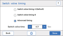
Follow the instructions below to set the Switch valve timing. For more details, refer to ÄKTA start Operating Instructions section Switch valve timing.
| Step | Action |
|---|---|
| 1 |
In the Settings and service screen, tap System. Result: The following screen opens. |
| 2 |
In the System screen, tap Switch valve timing. Result: The following screen opens. |
| 3 |
Tap the radio button to select Switch valve timing B (switch time 5 sec.). Tap Save to save the timing. |
| 4 | Perform Gradient run, either by performing System performance method or manually set the B concentration (Buffer valve) to 50%. Observe for the fluctuations. |
| 5 |
If wavy gradients still are obtained, or if fluctuations on step gradient levels are large, then select Advanced timing. Result: The following screen opens. Set switch valve time in the range of 3.0 to 5.0 sec (0.1 sec increments) by pressing the up/down arrows. |
| 6 |
Tap Save to save the optimized timing. |

Main board
|
NOTICE The Main board screen is reserved for operations performed by a Cytiva Service Engineer only. Do not perform any further operations from this screen. Tap Back or Home to return to the previous screen or to go to the Home screen. |
Disassembly
This section contains instructions how to disassembly, remove and replace all the modules that can be dis-assembled by the user.
Disassembly
The design of ÄKTA start allows all wet modules, except for the Pressure sensor, to easily be disassembled and reassembled by a user.
|
NOTICE Replacement of modules located on the inside of the instrument must be performed by a Cytiva Service Engineer only. If an internal part needs to be replaced, please contact a Cytiva Service Engineer. Internal modules include:
|
 |
WARNING To avoid personal injury when performing maintenance on ÄKTA start, follow the instructions below.
|
|
NOTICE Replacement of modules located on the wet side of the instrument must be performed by trained laboratory staff only. |
The illustration below shows the locations of the modules placed on the wet side of the instrument.
| Part | Module |
|---|---|
| 1 | Buffer valve |
| 2 | Mixer |
| 3 | Sample valve |
| 4 | Pump |
| 5 | Pressure sensor |
| 6 | Wash valve |
| 7 | Injection valve |
| 8 | UV |
| 9 | Conductivity |
| 10 | Outlet valve |
Note: In case of multiple valve failures, make sure that the valves are not mixed. Replace the valves one by one by removing one valve at a time from the instrument.
Required tools
| Tool | Dimension |
|---|---|
| Torx driver | T10 |
Instructions
Follow the instructions below to remove and replace the Buffer valve.
|
WARNING Disconnect power. Always switch off power to the instrument before replacing any component on the instrument or cleaning the instrument, unless stated otherwise in the user documentation. |
| Step | Action |
|---|---|
| 1 | Switch off the instrument by pressing the Power Switch to the O position. |
| 2 | Remove the inlet and outlet tubing from the valve ports. |
| 3 |
Loosen the M3 screw from the valve using a T10 torx driver, supplied with the equipment at delivery. Note: The screw can be located on different places on the top circumference of the holder. |
| 4 | Slowly remove the Buffer valve until a cable is visible. The cable is assembled with two connectors interconnected. |
| 5 | Press on the connector and remove the connector and cable. |
| 6 | Disconnect the connector from the valve side. |
| 7 | Remove the valve and leave the connector as it is. |
| 8 |
Replace with a new Buffer valve, connect the cable, and reconnect the tubing to the valve ports. Note: Before replacing the valve, make sure that the part number (P/N) on the new valve matches with that of the old valve (29003271, Buffer valve CTV-31-516U-1). |
| 9 | Make sure that the ports are aligned to the markings on the instrument chassi. |
| 10 | Switch on the instrument by pressing the Power Switch to the l position. |
Required tools
| Tool | Dimensions |
|---|---|
| Torx screwdriver | T20 |
Instructions
Follow the instructions below to remove and replace the Mixer.
|
WARNING Disconnect power. Always switch off power to the instrument before replacing any component on the instrument or cleaning the instrument, unless stated otherwise in the user documentation. |
| Step | Action |
|---|---|
| 1 | Switch off the instrument by pressing the Power Switch to the O position. |
| 2 | Remove the inlet and outlet tubing from the ports. |
| 3 | Loosen the M4 screw from the Mixer using a T20 screwdriver, supplied with the equipment at delivery. |
| 4 | Remove the Mixer. |
| 5 | Replace with a new Mixer and reconnect the tubing to the ports. |
| 6 | Switch on the instrument by pressing the Power Switch to the l position. |
Required tools
| Tool | Dimensions |
|---|---|
| Torx screwdriver | T20 |
Instructions
Follow the instructions below to remove and replace the UV Monitor.
|
WARNING Disconnect power. Always switch off power to the instrument before replacing any component on the instrument or cleaning the instrument, unless stated otherwise in the user documentation. |
| Step | Action |
|---|---|
| 1 | Switch off the instrument by pressing the Power Switch to the O position. |
| 2 | Remove the inlet and outlet tubing from the ports. |
| 3 | Unscrew the one screw at the top of the UV Monitor, and then the two screws at the bottom using a T20 screwdriver, supplied with the equipment at delivery. |
| 4 | Slowly remove the UV Monitor until you get access to the RJ45 connector plugged into the module. |
| 5 |
Disconnect the RJ45 connector from the UV Monitor side. Note: Make sure that the RJ45 connector is not moved inside the cabinet. The connector needs to be retained outside the cabinet for re-assembling of a new UV module. |
| 6 | Remove the UV Monitor and leave the RJ45 connector as it is. |
| 7 | Replace with a new UV Monitor by connecting the RJ45 connector and then reconnect the tubing to the ports. |
| 8 | Switch on the instrument by pressing the Power Switch to the l position. |
Instructions
Follow the instructions below to remove and replace the UV flow cell.
| Step | Action |
|---|---|
| 1 | Disconnect the inlet and outlet tubing from the UV Monitor. |
| 2 | Rotate the locknut in the anticlockwise direction. |
| 3 | Pull up the UV flow cell. |
| 4 | Put a new UV flow cell in place from above so that it fits in properly, and simultaneously tighten the locknut. |
| 5 |
Place the protective cover around the flow cell to protect the electronics inside the optical unit from liquid spillage. Note: The protective cover should be assembled after completing the assembly of the UV flow cell inside the UV Monitor by just press-fit. |
| 6 |
In the Settings and Service screen, tap UV. In the UV screen, perform a UV LED calibration and a Flow cell path length test. This is described further in the "Access the modules" section above. |
Required tools
| Tool | Dimension |
|---|---|
| Torx driver | T10 |
Instructions
Follow the instructions below to remove and replace the Sample valve.
|
WARNING Disconnect power. Always switch off power to the instrument before replacing any component on the instrument or cleaning the instrument, unless stated otherwise in the user documentation. |
| Step | Action |
|---|---|
| 1 | Switch off the instrument by pressing the Power Switch to the O position. |
| 2 | Remove the inlet and outlet tubing from the ports. |
| 3 |
Loosen the screw from the valve using a T10 torx driver, supplied with the equipment at delivery. Note: The screw can be locate on different places on the top circumference of the holder. |
| 4 | Slowly remove the Sample valve until a cable is visible. The cable is assembled with two connectors interconnected. |
| 5 | Disconnect the connector from the valve side. |
| 6 | Remove the Sample valve. |
| 7 |
Replace with a new Sample valve, connect the cable, and reconnect the tubing to the valve ports. Note: Before replacing the valve, make sure that the part number (P/N) on the new valve matches with that of the old valve (29003272, Sample valve CTV-31-32U-3). |
| 8 | Make sure that the ports are aligned to the markings on the instrument chassi. |
| 9 | Switch on the instrument by pressing the Power Switch to the l position. |
Required tools
| Tool | Dimensions |
|---|---|
| Torx driver | T20 |
Instructions
Follow the instructions below to remove and replace the Pump.
|
WARNING Disconnect power. Always switch off power to the instrument before replacing any component on the instrument or cleaning the instrument, unless stated otherwise in the user documentation. |
|
NOTICE Keep the pump cover open when not using the system. Open the peristaltic pump cover after you switch off the equipment. This reduces the risk of shortening the life time of the pump tubing. |
| Step | Action |
|---|---|
| 1 | Switch off the instrument by pressing the Power Switch to the O position. |
| 2 | Open the top cover to remove the tubing from the Pump. |
| 3 |
Loosen the two M4 screws from the Pump using a T20 screwdriver, supplied with the equipment at delivery. Note: Make sure that the pump connector is not moved inside the cabinet. The connector needs to be retained outside the cabinet for re-assembling of a new Pump module. |
| 4 | Slowly remove the Pump until a cable is visible. The cable is assembled with two connectors interconnected. |
| 5 | Disconnect the connector from the Pump side. |
| 6 |
Remove the Pump. Note: Make sure that the pump cable is placed away from the fan, on the left side of the instrument after removing the Pump. This safety precautions is to ensure that the cable does not get stuck in the ventilation fan. |
| 7 | Replace with a new Pump, install the new Pump in reverse order. |
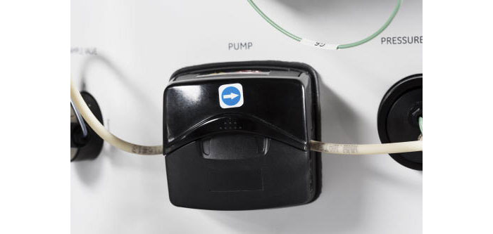
| 8 | Place the Pump tubing between the rollers and the track of the new Pump. |
| 9 | Switch on the instrument by pressing the Power Switch to the l position. |
| 10 | In the Pump screen, tap Diagnostics and then reset the number of hours of Pump run to 0. |
Instructions
Follow the instructions below to remove and replace the pump tubing.
|
WARNING Disconnect power. Always switch off power to the instrument before replacing any component on the instrument or cleaning the instrument, unless stated otherwise in the user documentation. |
| Step | Action |
|---|---|
| 1 | Switch off the instrument by pressing the Power Switch to the O position. |
| 2 | Open the top cover until it is fully open. |
| 3 |
Place the tubing between the rollers and the track, press against the pump head inner wall. Note: Make sure that the pump tubing is not twisted or stretched against the rollers. |
| 4 |
Lower the flip top until it clicks into its fully closed position. The track closes automatically and the tubing is stretched correctly as the track closes. |
| 5 | Connect the pump tubing to the Sample valve and to the Pressure sensor. |
| 6 | Switch on the instrument by pressing the Power Switch to the l position. |
Required tools
| Tool | Dimensions |
|---|---|
| Torx driver | T10 |
Instructions
Follow the instructions below to remove and replace the Wash valve.
|
WARNING Disconnect power. Always switch off power to the instrument before replacing any component on the instrument or cleaning the instrument, unless stated otherwise in the user documentation. |
| Step | Action |
|---|---|
| 1 | Switch off the instrument by pressing the Power Switch to the O position. |
| 2 | Remove the inlet and outlet tubing from the ports. |
| 3 |
Loosen the M3 screw from the Wash valve using a T10 torx driver, supplied with the equipment at delivery. Note: The screw can be located on different places on the top circumference of the holder. |
| 4 | Slowly remove the Wash valve until a cable is visible. The cable is assembled with two connectors interconnected. |
| 5 | Disconnect the connector from the valve side. |
| 6 | Remove the Wash valve from the instrument. |
| 7 | Replace with a new Wash valve. Connect the cable, and then reconnect the tubing to the valve ports. |
| 8 | Make sure that the ports are aligned to the markings on the instrument chassi. |
| 9 | Switch on the instrument by pressing the Power Switch to the l position. |
Required tools
| Tool | Dimensions |
|---|---|
| Torx driver | T10 |
Instructions
Follow the instructions below to remove and replace the Outlet valve.
|
WARNING Disconnect power. Always switch off power to the instrument before replacing any component on the instrument or cleaning the instrument, unless stated otherwise in the user documentation. |
| Step | Action |
|---|---|
| 1 | Switch off the instrument by pressing the Power Switch to the O position. |
| 2 | Remove the inlet and outlet tubing from the ports. |
| 3 |
Loosen the M3 screw from the Outlet valve using a T10 torx driver, supplied with the equipment at delivery. Note: The screw can be located on different places on the top circumference of the holder. |
| 4 | Slowly remove the Outlet valve until a cable is visible. The cable is assembled with two connectors interconnected. |
| 5 | Disconnect the connector from the valve side. |
| 6 | Remove the Outlet valve. |
| 7 |
Replace with a new Outlet valve. Connect the cable, and then reconnect the tubing to the valve ports. Note: Before replacing the valve, make sure that the part number on the new valve matches with that of the old valve (29003274 Outlet valve CTV-31-32U-1). |
| 8 | Make sure that the ports are aligned to the markings on the instrument chassi. |
| 9 | Switch on the instrument by pressing the Power Switch to the l position. |
Required tools
| Tool | Dimensions |
|---|---|
| Torx screwdriver | T20 |
Instructions
Follow the instructions below to remove and replace the Conductivity Monitor.
|
WARNING Disconnect power. Always switch off power to the instrument before replacing any component on the instrument or cleaning the instrument, unless stated otherwise in the user documentation. |
Note: If required, twist the connector to bring the connector out of the instrument hole, before disassembly the Conductivity Monitor.
| Step | Action |
|---|---|
| 1 | Switch off the instrument by pressing the Power Switch to the O position. |
| 2 | Remove the inlet and outlet tubing from the ports. |
| 3 | Loosen the M4 screws from the Conductivity Monitor using a T20 screwdriver, supplied with the equipment at delivery. |
| 4 | Slowly remove the Conductivity Monitor until a cable is visible. The cable is assembled with two connectors interconnected. |
| 5 | Disconnect the connector from the Conductivity Monitor side. |
| 6 |
Remove the Conductivity Monitor and leave the connector as it is. Note: Make sure that the connector is not moved inside the cabinet. The connector needs to be retained outside the cabinet for re-assembling of a new Conductivity module. |
| 7 | Replace with a new Conductivity Monitor and reconnect the tubing to the ports. |
| 8 | Switch on the instrument by pressing the Power Switch to the l position. |
| 9 | In the Settings and service screen, access the Conductivity screen to set the cell constant for the new Conductivity flow cell. For details, see Access the modules section. |
Required tools
| Tool | Dimensions |
|---|---|
| Torx driver | T10 |
Instructions
Follow the instructions below to remove and replace the Injection valve.
|
WARNING Disconnect power. Always switch off power to the instrument before replacing any component on the instrument or cleaning the instrument, unless stated otherwise in the user documentation. |
| Step | Action |
|---|---|
| 1 | Switch off the instrument by pressing the Power Switch to the O position. |
| 2 | Remove the inlet and outlet tubing from the ports. |
| 3 | Loosen the M3 screw from the Injection valve using a T10 torx driver, supplied with the equipment at delivery. |
| 4 | Remove the Injection valve. |
| 5 | Replace with a new Injection valve and reconnect the tubing to the ports. |
| 6 | Make sure that the ports are aligned to the markings on the instrument chassi. |
| 7 | Switch on the instrument by pressing the Power Switch to the l position. |
Required tools
| Tool | Dimensions |
|---|---|
| Torx driver | T10 |
Instructions
Follow the instructions below to remove and replace the Injection valve kit.
| Step | Action |
|---|---|
| 1 | Make sure that the valve is in position: Inject, and then disconnect the inlet and outlet tubing from the ports. |
| 2 | Remove the 3 screws on the front side, using the supplied torx driver. Loosen each screw equally in turn, so the distribution plate comes off in parallel to the valve body. |
| 3 | Slide the screws out. |
| 4 | Remove the distribution plate containing the ports. |
| 5 | Remove the old channel plate and insert a new one. |
| 6 | Remount a new distribution plate so that the marks on the plate match the marks on ÄKTA start. Using the torx driver, tighten the 3 screws in turn, a little at a time, until the distribution plate is fixed to the valve body. |
Remove the Bowl assembly
Follow the instructions below to remove the Frac30 Bowl assembly.
| Step | Action |
|---|---|
| 1 | Gently move the Dispenser arm counterclockwise to the non-dispensing (end) position. |
| 2 | Push the drive assembly laterally and hold it at the retracted position. |
| 3 | Lift and remove the Bowl assembly. |
Mount the Bowl assembly onto the Bowl holder
Follow the instructions below to mount the Frac30 Bowl assembly onto the Bowl holder.
| Step | Action |
|---|---|
| 1 | Make sure that the Dispenser arm is in the non-dispensing position. |
| 2 | Note the position of the aligning groove on the Bowl holder. |
| 3 | Note the position of the aligning ribs on the Bowl. |
| 4 |
Hold the Bowl assembly and orient the Bowl with the aligning ribs oriented towards the aligning groove on the Bowl holder. Note: Do not lift the fraction collector by holding the Dispenser arm. |
| 5 | After locating the aligning features, leave the Bowl to slide freely into the Bowl holder. |
| 6 | Hold the Drive assembly at the retracted position to completely assemble the Bowl assembly on the Bowl holder. |
Remove and fix the drive sleeve
Follow the instructions below to remove and replace the drive sleeve.
| Step | Action |
|---|---|
| 1 | Cut the old drive sleeve with a cutter, and then remove the drive sleeve. |
| 2 | Mount a new drive sleeve by pressing and sliding it onto the drive. |
Remove and fix the Tubing holder
Follow the instructions below to remove and replace the Tubing holder.
| Step | Action |
|---|---|
| 1 | Pull out the Tubing holder from the Dispenser arm. |
| 2 | Press down the new Tubing holder into the Dispenser arm until it is stopped by the dispensing arm stopping feature. |
Required tools
| Tools | Dimensions |
|---|---|
| Flat screwdriver | - |
Remove the Fuse
Follow the instructions below to remove the Fuse.
| Step | Action |
|---|---|
| 1 | Use the flat screwdriver provided, and push the Snap feature on the left side of the Fuse holder, in the direction indicated by the arrow mark. |
| 2 | Use the flat screwdriver, and push the Snap feature on the right side of the Fuse holder, in the direction indicated by the arrow mark. |
| 3 | It should now be possible to slide out the Fuse from the holder, pull out the Fuse by hand. |
Mount the Fuse
Follow the instructions below to replace the Fuse.
| Step | Action |
|---|---|
| 1 | Align the Fuse holder guide feature to the rectangular slot of the Mains filter. |
| 2 | Push the Fuse holder into the rectangular slot until it fits into the rectangular groove of the Mains filter. |