
ÄKTA pure™ 150 M
ÄKTA pure system with pumps, injection valve, and pressure, UV, and conductivity monitors.
FAQ
Why should I have REGULAR, PLANNED MAINTENANCE on my system?
With the pressure on producing sample or results, the condition of your ÄKTAdesign or Ettan system is critical and regular servicing will mean you can depend on your system to perform as expected. Planned maintenance can be part of a service agreement, scheduled to service your system before it is in need of attention. We can help you design a schedule and routine to allow you to maintain your system, please contact your local Cytiva service representative.
So what can you expect from a planned maintenance visit from Cytiva service representative?
- Thorough inspection and cleaning of system components
- Update of system firmware to ensure full compatibility of your system and UNICORN software
- Replacement of damaged or corroded seals, valve springs and solenoids
- Replacement of items that are reaching the end of their expected life – preventing future breakdowns
- Advice and guidance on proper daily use, cleaning and care of your system
- All work is documented and reported to help make any regulatory audits easier.
A complete overhaul, once a year, ensures that your instrument is running at peak performance so you can be confident of your scientific results. In addition, wear and tear on systems under constant use by multiple end users is minimized, giving the system a longer life and better value for money.
To find out more about service possibilities contact your local Cytiva service representative.
Tricorn 5, High Performance Column
Tricorn 10, High Performance Column
HiScale 16
HiScale 26
HiScale 50
XK 16
XK 26
XK 50
I want to know the FLOW and PRESSURE RANGE of my system.
| System | Height (mm) |
Footprint (mm x mm) |
Weight (kg) |
Flow rate (ml/min) |
Pressure limit (MPa) |
|---|---|---|---|---|---|
| ÄKTA avant 25 | 660 | 860 x 710 | 116 | 0.001-25 | 20 |
| ÄKTA avant 150 | 660 | 860 x 710 | 116 | 0.001-150 (normal range) 0.001-300 (column packing flow) |
5 |
| ÄKTA pure | 630 | 535 x 470 | up to 53 kg | 0.001 to 25 (up to 50 during column packing) |
20 |
| ÄKTA pure 150 | 630 | 535 x 470 | up to 53 kg | 0.01 to 25 (up to 300 during column packing) |
5 |
| ÄKTAexplorer 10 | 620 | 500 x 460 | 75 | 0.001-10 | 25 |
| ÄKTAexplorer 100 | 620 | 500 x 460 | 75 | 0.01-100 | 10 |
| ÄKTAFPLC | 470 | 380 x 480 | 50 | 0.05-20 | 5 |
| ÄKTAmicro | 610 | 480 x 450 | 55 | 0.001-2 | 35 |
| ÄKTApilot | 900 | 750 x 540 | 114 | 4-400 (full gradients) 4-800 (limited gradients) |
2 |
| ÄKTAprime plus | 530 | 400 x 450 | 13 | 0.1-50 | 1 |
| ÄKTApurifier 10 | 620 | 500 x 460 | 75 | 0.001-10 | 25 |
| ÄKTApurifier 100 | 620 | 500 x 460 | 75 | 0.01-100 | 10 |
| ÄKTAxpress | 660 | 490 x 250 | 30 | 0.1-65 | 3 |
| Ettan LC | 610 | 480 x 450 | 55 | 0.001-2 | 35 |
| Ettan MDLC | 710 | 700 x 640 | 105 | 0.001-2 | 35 |
| Ettan microLC | 1150 | 650 x 500 | 77 | 0.001-2 |
35
|
| Ettan nanoLC | 1150 | 650 x 500 | 77 | 0.001-2 | 35 |
I want to know the DIMENSIONS and WEIGHT of my system.
| System | Height (mm) |
Footprint (mm x mm) |
Weight (kg) |
Flow rate (ml/min) |
Pressure limit (MPa) |
|---|---|---|---|---|---|
| ÄKTA avant 25 | 660 | 860 x 710 | 116 | 0.001-25 | 20 |
| ÄKTA avant 150 | 660 | 860 x 710 | 116 | 0.001-150 (normal range) 0.001-300 (column packing flow) |
5 |
| ÄKTA pure | 630 | 535 x 470 | up to 53 kg | 0.001 to 25 (up to 50 during column packing) |
20 |
| ÄKTA pure 150 | 630 | 535 x 470 | up to 53 kg | 0.01 to 150 (up to 300 during column packing) |
5 |
| ÄKTAexplorer 10 | 620 | 500 x 460 | 75 | 0.001-10 | 25 |
| ÄKTAexplorer 100 | 620 | 500 x 460 | 75 | 0.01-100 | 10 |
| ÄKTAFPLC | 470 | 380 x 480 | 50 | 0.05-20 | 5 |
| ÄKTAmicro | 610 | 480 x 450 | 55 | 0.001-2 | 35 |
| ÄKTApilot | 900 | 750 x 540 | 114 | 4-400 (full gradients) 4-800 (limited gradients) |
2 |
| ÄKTAprime plus | 530 | 400 x 450 | 13 | 0.1-50 | 1 |
| ÄKTApurifier 10 | 620 | 500 x 460 | 75 | 0.001-10 | 25 |
| ÄKTApurifier 100 | 620 | 500 x 460 | 75 | 0.01-100 | 10 |
| ÄKTAxpress | 660 | 490 x 250 | 30 | 0.1-65 | 3 |
| Ettan LC | 610 | 480 x 450 | 55 | 0.001-2 | 35 |
| Ettan MDLC | 710 | 700 x 640 | 105 | 0.001-2 | 35 |
| Ettan microLC | 1150 | 650 x 500 | 77 | 0.001-2 |
35
|
| Ettan nanoLC | 1150 | 650 x 500 | 77 | 0.001-2 | 35 |
ÄKTA pure Operating Instructions (English), printed copy
ÄKTA pure Product Documentation (material specification and EC declaration of conformance)
Documentation CD: Translated versions of Operating Instructions (PDF) and ÄKTA pure System Handbook (PDF)
Instrument configuration CD
Purifying some samples at room temperature can lead to increased levels of degradation; performing your purifications at 4C can help. All our ÄKTA systems, Ettan LC, Ettan microLC, Ettan nanoLC and fraction collectors are suitable for use in the temperature range of 4-40C.
The computer systems are not however cold room compatible, and can be damaged by being placed at 4C.
When installing an ÄKTA system in a cold room the computer can be positioned up to 15 m away, allowing it to be positioned outside the cold room. Cold cabinets can provide an effective solution to running your ÂKTA system in the cold whilst protecting the PC. When moving a system to or from a cold room, time must be allowed for the system to adjust to its new temperature. You may also find that you need to tighten the connectors on your system slightly to prevent leaks when you bring a system out from the cold, and loosen them slightly before you put a system into the cold to prevent pressure build up.
Changes in temperature can also affect the viscosity of your buffers so keep a close eye on your back pressure.
This section specifies the chemical resistance of ÄKTA pure to some of the most commonly used chemicals in liquid chromatography.
Assumptions made
The ratings are based on the following assumptions:
- Synergy effects of chemical mixtures have not been taken into account.
- Room temperature and limited overpressure is assumed.
Chemical influences are time and pressure dependent. Unless otherwise stated, all concentrations are 100%.
List of chemicals
Proposed chemical compatibility for ÄKTA pure. All chemicals used for CIP and cleaning are for short term use only, ambient temperature < 25ºC, if not other stated.
Note: A user can be exposed to large volumes of chemical substances over a long time period. A Material Safety Data Sheet (MSDS) provides the user with information regarding characteristics, human and environmental risks and preventive measures. Make sure that you have the MSDS available from your chemical distributor and/or databases on the internet.
| Chemical | Concentration | CAS no/ EC no |
|---|---|---|
| Aqueous buffers, pH 2-12 | - | N/A |
| Acetic acid | 70% | 64-19-7/ 200-580-7 |
|
Acetonitrile1 Depending on pressure, tubing between pump head and pressure monitor needs to be changed. See ÄKTA pure System Handbook, chapter Prepare the system for a run. |
100% | 75-05-8/ 200-835-2 |
| Acetonitrile/Tetrahydrofuran (THF) | 85/15 | 109-99-9/ 203-726-8 |
| Acetone | 10% | 67-64-1/ 200-662-2 |
| Ammonia | 30% | 7664-41-7/ 231-635-3 |
| Ammonium chloride | 2 M | 12125-02-9/ 235-186-4 |
| Ammonium sulphate | 3 M | 7783-20-2/ 231-984-1 |
| Arginine | 2 M | 74-79-3/ 200-811-1 |
| Benzyl alcohol | 2% | 100-51-6/ 202-859-9 |
| Decon™ 90 | 10% | N/A |
| Dimethyl sulphoxide (DMSO) | 5% | 67-68-5/ 200-664-3 |
| Dithiothreitol (DTT) | 100 mM | 3483-12-3 / 222-468-7 |
| Dithioerythritol (DTE) | 100 mM | 6892-68-8/ 229-998-8 |
| Ethylenediaminetetraaceticacid (EDTA) | 100 mM | 60-00-4/ 200-449-4 |
| Ethanol | 20% | 75-08-1/ 200-837-3 |
| Ethanol | 96% | 75-08-1/ 200-837-3 |
| Ethanol + NaOH | 40% + 1 M | N/A |
| Ethylene glycol | 50% | 107-21-1/ 203-473-3 |
| Formic acid | 1% | 64-18-6/ 200-579-1 |
| Glycerol | 50% | 56-81-5/ 200-289-5 |
| Glycine | 2 M | 56-40-6/ 200-272-2 |
| Guanidinium hydrochloride | 6 M | 50-01-1/ 200-002-3 |
| Hydrochloric acid2 | max. 0.1 M | 7647-01-0/ 231-595-7 |
| Imidazole | 2 M | 288-32-4/ 206-019-2 |
| Isopropanol | 100% | 67-63-0/ 200-661-7 |
| Methanol | 100% | 74-93-1/ 200-659-6 |
| Mercaptoethanol | 20 mM | 37482-11-4/ 253-523-3 |
| n-Propanol | 50% | 67-63-0/ 200-661-7 |
| Phosphoric acid | 0.1 M | 7664-38-2/ 231-633-2 |
| Potassium phosphate | 1 M | 7778-77-0/ 231-913-4 |
| Potassium chloride | 4 M | 7447-40-7/ 231-211-8 |
| Sodium dodecyl sulfate (SDS) | 1% | 151-21-3/ 205-788-1 |
| Sodium chloride | 4 M | 7647-14-5/ 231-598-3 |
| Sodium hydroxide | 2 M | 1310-73-2/ 215-185-5 |
| Sodium sulphate | 1 M | 7757-82-6/ 231-820-9 |
| Trichloroacetic acid | 1% | 76-03-9/ 200-927-2 |
| Trifluoroacetic acid | 1% | 176-05-1/ 200-929-3 |
| Triton™ X-100 | 1% | 9002-93-1 |
| Tween 20 | 1% | 9005-64-5/ 500-018-3 |
| Urea | 8 M | 57-13-6/ 200-315-5 |
| Water | 100% | 7732-18-5/ 231-791-2 |
1 PEEK tubing is biocompatible and chemically inert to most solvents used in the purification of proteins. It has in general very good pressure limits, especially for water based buffers. However, organic solvents can penetrate weaknesses in the tubing walls more easily than water based buffers. Special care should therefore be taken with prolonged use of organic solvents close to pressure limits.
2 If hydrochloric acid, HCl, is used as a cleaning agent when columns are connected to the system, the HCl concentration should not exceed 0.1 M in the System pressure monitor or in the pressure monitor in Column valve V9-C.
For other parts of the system up to 1 M HCl is acceptable for short time use.
For cleaning of columns with HCl concentrations exceeding 0.1 M, manually fill a loop with HCl and inject the cleaning agent.
Spare parts
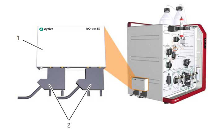
Location of the I/O box
The illustration below shows the I/O-box and its recommended location and connection points.
Function of the I/O-box
The I/O-box E9 is used to interface other equipment in order to measure parameters such as refractive index, light scattering and fluorescence. See Requirements on connected equipment, on page 196 for information on requirements of the equipment that can be connected to ÄKTA pure. The I/O-box can control external equipment by a digital output signal, as well as detecting the state of them by digital inputs. It is possible to install up to two I/O-box E9 when using ÄKTA pure. If two I/O-boxes are to be used, the second one has to be configured as I/O-box E9, 2nd. The configuration is defined by the I/O-box E9 Node ID.
| Part | Description |
|---|---|
| 1 | I/O-box |
| 2 | D-sub connectors |
| # | Product Name | Product Code | Price | |
|---|---|---|---|---|
| I/O-box E9 | 29011361 | 2,842.00 USD |
Add to cart
|
| # | Product Name | Product Code | Price | |
|---|---|---|---|---|
| 1 | Module Panel | 29011364 | 205.00 USD |
Add to cart
|
| 2 | Multi-module panel | 29011351 | 724.00 USD |
Add to cart
|
| # | Product Name | Product Code | Price | |
|---|---|---|---|---|
| 1 | Jumper 1 IEC 1394 | 28956489 | 53.82 USD |
Add to cart
|
| 2 | Jumper D-Sub | 29011365 | 187.33 USD |
Add to cart
|
| 4 | External module cable | 29011366 | 173.88 USD |
Add to cart
|
| 5 | Cable 2.5m UniNet-9 D-type | 29032425 | 140.76 USD |
Add to cart
|
| # | Product Name | Product Code | Price | |
|---|---|---|---|---|
| Inlet filter holder kit | 11000407 | 167.67 USD |
Add to cart
|
|
| Inlet filter set | 11000414 | 109.71 USD |
Add to cart
|
|
| Tubing cutter, for PEEK, EFTE, and FEP tubing i.d. 0.25, 0.5, 0.75, 1 and 1.6 mm | 18111246 | 99.55 USD |
Add to cart
|
|
| Reference capillary 1 | 28950749 | 136.97 USD |
Add to cart
|
|
| Reference capillary 2 | 28950750 | 136.97 USD |
Add to cart
|
|
| Union 1/16 male/male, i.d. 0.5 mm | 28954326 | 164.56 USD |
Add to cart
|
|
| ETFE Tubing Kit 10 x 1.0 m, i.d. 1.0 mm, o.d. 1/16" | 28980995 | 202.00 USD |
Add to cart
|
|
| Tubing Kit, 0.50 mm | 29011327 | 1,137.00 USD |
Add to cart
|
|
| Tubing Kit, 0.25 mm | 29011328 | 1,140.00 USD |
Add to cart
|
|
| Tubing Kit, 0.75 mm | 29011329 | 1,137.00 USD |
Add to cart
|
|
| Tubing kit for inlet valve V9-IAB | 29011330 | 292.00 USD |
Add to cart
|
|
| Tubing kit for V9-pH, standard | 29011331 | 284.00 USD |
Add to cart
|
|
| Tubing kit for V9-IA (7-ports) | 29011332 | 308.00 USD |
Add to cart
|
|
| Tubing kit for V9-IB (7-ports) | 29011333 | 307.00 USD |
Add to cart
|
|
| Tubing kit for outlet fractionation (10 outlets) | 29011334 | 275.00 USD |
Add to cart
|
|
| System Pump Rinse Tubing Kit | 29011348 | 140.76 USD |
Add to cart
|
|
| Tubing Kit i.d. 1.0 mm | 29032426 | 1,161.00 USD |
Add to cart
|
|
| Tubing kit for Sample Inlet Valve V9-IS | 29035331 | 307.00 USD |
Add to cart
|
|
| System Tubing kit for ÄKTA pure 150, i.d. 0.75 mm | 29048242 | 1,140.00 USD |
Add to cart
|
|
| Tubing Kit for Outlet Fractionation (10 outlets) | 29048611 | 275.00 USD |
Add to cart
|
|
| Tubing kit for Sample Inlet Valve V9H-IS | 29051166 | 307.00 USD |
Add to cart
|
|
| Tubing kit for V9H-IB (7-ports) | 29051189 | 307.00 USD |
Add to cart
|
|
| Tubing kit for V9H-IA (7-ports) | 29051197 | 307.00 USD |
Add to cart
|
|
| System Tubing kit for ÄKTA pure 150, i.d. 0.50 mm | 29051669 | 1,137.00 USD |
Add to cart
|
|
| V9H-pH Tubing Kit | 29051674 | 274.00 USD |
Add to cart
|
Location and illustration of pumps
The illustration below shows the location of System pump A and System pump B, together with a detailed view of a system pump. System pump A is labeled P9 A and System pump B is labeled P9 B.
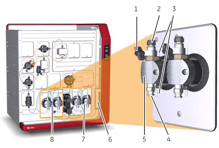
| Part | Description |
|---|---|
| 1 | Purge valve: Used to remove air from the pump |
| 2 | Outlet port with check valve |
| 3 | Connections to pump piston rinsing system: Tubing is connected between the pumps and the Pump piston rinsing system tube (6) |
| 4 | Inlet port with check valve |
| 5 | Pump head: Encapsulates the inner parts of the pump |
| 6 | Pump piston rinsing system tube |
| 7 | System pump B |
| 8 | System pump A |
| # | Product Name | Product Code | Price | |
|---|---|---|---|---|
| Check valve kit | 18112866 | 1,398.00 USD |
Add to cart
|
|
| Piston kit, 25 ml | 28952640 | 935.00 USD |
Add to cart
|
|
| P9 Seal kit, 25 ml | 28952642 | 693.00 USD |
Add to cart
|
|
| P9H Check valve kit | 28979364 | 1,141.00 USD |
Add to cart
|
|
| P9H Piston kit 150 ml | 28979368 | 912.00 USD |
Add to cart
|
|
| P9H Seal kit 150 ml | 28979373 | 729.00 USD |
Add to cart
|
|
| Sample Pump S9H | 29050593 | 9,294.00 USD |
Add to cart
|
Typical configuration of an ÄKTA pure 25 (25 ml/min) system.
| # | Product Name | Product Code | Price | |
|---|---|---|---|---|
| 1 | Inlet Valve Kit V9-IA | 29012263 | 6,516.00 USD |
Add to cart
|
| 3 | Check valve kit | 18112866 | 1,398.00 USD |
Add to cart
|
| 3 | P9 Seal kit, 25 ml | 28952642 | 693.00 USD |
Add to cart
|
| 5 | Check valve kit | 18112866 | 1,398.00 USD |
Add to cart
|
| 5 | Piston kit, 25 ml | 28952640 | 935.00 USD |
Add to cart
|
| 5 | P9 Seal kit, 25 ml | 28952642 | 693.00 USD |
Add to cart
|
| 6 | Online filter kit | 18102711 | 144.90 USD |
Add to cart
|
| 6 | O-ring 13.1x1.6 mm | 28953545 | 86.95 USD |
Add to cart
|
| 6 | Mixer chamber 0.6 ml | 28956186 | 1,355.00 USD |
Add to cart
|
| 6 | Mixer chamber 1.4 ml | 28956225 | 1,370.00 USD |
Add to cart
|
| 6 | Mixer chamber 5 ml | 28956246 | 1,370.00 USD |
Add to cart
|
| 6 | O-ring 13.1 x 1.6 mm High resistance | 29011326 | 205.00 USD |
Add to cart
|
| 6 | Outlet Valve Kit V9-Os | 29011356 | 2,483.00 USD |
Add to cart
|
| 7 | Outlet valve kit V9-O | 29012261 | 4,295.00 USD |
Add to cart
|
| 8 | Injection Valve, V9-Inj | 28956514 | 4,069.00 USD |
Add to cart
|
| 9 | Conductivity monitor (C9n) | 29011363 | 2,909.00 USD |
Add to cart
|
| 10 | Column Valve V9-Cs | 29011355 | 3,701.00 USD |
Add to cart
|
| 10 | Column Valve kit V9-C | 29011367 | 8,734.00 USD |
Add to cart
|
| 11 | UV flow cell, 5 mm, for U9-L | 18112824 | 2,622.00 USD |
Add to cart
|
| 11 | UV flow cell, 5 mm, for U9-L | 18112824 | 2,622.00 USD |
Add to cart
|
| 11 | UV flow cell, 10 mm, for U9-M | 28956378 | 2,375.00 USD |
Add to cart
|
| 11 | UV flow cell, 2 mm, for U9-M | 28979380 | 3,530.00 USD |
Add to cart
|
| 11 | UV flow cell, 0.5 mm, for U9-M | 28979386 | 3,667.00 USD |
Add to cart
|
| 11 | UV flow cell, 2 mm, for U9-L | 29011325 | 2,835.00 USD |
Add to cart
|
| 11 | UV flow cell, 2 mm, for U9-L | 29011325 | 2,835.00 USD |
Add to cart
|
| 11 | UV Monitor U9-L | 29011360 | 6,564.00 USD |
Add to cart
|
| 11 | UV monitor U9-T | 29710522 | 12,600.00 USD |
Add to cart
|
| 12 | Multi-module panel | 29011351 | 724.00 USD |
Add to cart
|
| 13 | Tube Rack 40 × 30 mm, bowl, tube support, holder and guide | 18112467 | 609.00 USD |
Add to cart
|
| 13 | Tube Holder and Guide, 40 × 30 mm | 18112468 | 520.00 USD |
Add to cart
|
| 13 | Tube Rack Complete, 95 × 10–18 mm | 18305003 | 681.00 USD |
Add to cart
|
| 13 | Bowl | 18305103 | 205.00 USD |
Add to cart
|
| 13 | Tube Support | 18305402 | 154.21 USD |
Add to cart
|
| 13 | Tubing Holder | 18646401 | 99.36 USD |
Add to cart
|
| 13 | Drive sleeve | 19606702 | 133.07 USD |
Add to cart
|
| 13 | Tube Holder and Guide, 175 × 12 mm | 19724202 | 419.00 USD |
Add to cart
|
| 13 | Tube Rack 175 × 12 mm, bowl, tube support, holder and guide | 19868403 | 494.00 USD |
Add to cart
|
| 13 | Tube Holder and Guide, 95 × 10–18 mm | 19868902 | 275.00 USD |
Add to cart
|
| 13 | Fraction Collector F9-R | 29011362 | 4,270.00 USD |
Add to cart
|
Accessories
| # | Product Name | Product Code | Price | |
|---|---|---|---|---|
| 1 | Adapter for air sensor | 28956342 | 171.81 USD |
Add to cart
|
| 2 | Bottle holder | 28956327 | 306.00 USD |
Add to cart
|
| 3 | Column Clamp | 28956319 | 83.84 USD |
Add to cart
|
| 4 | Column Holder | 28956282 | 138.69 USD |
Add to cart
|
| 5 | Column Holder Rod | 28956270 | 1,017.00 USD |
Add to cart
|
| 6 | Flexible column holder | 28956295 | 1,480.00 USD |
Add to cart
|
| 7 | Loop Holder | 29011350 | 910.00 USD |
Add to cart
|
| 8 | Multi-Purpose Holder | 29011349 | 79.69 USD |
Add to cart
|
| 9 | Rail Extension | 29011352 | 443.00 USD |
Add to cart
|
| 10 | Tube holder | 28954329 | 52.78 USD |
Add to cart
|
| 11 | Tubing holder, comb | 28956286 | 83.84 USD |
Add to cart
|
| 12 | Tubing holder, spool, for small tubing | 28956274 | 83.84 USD |
Add to cart
|
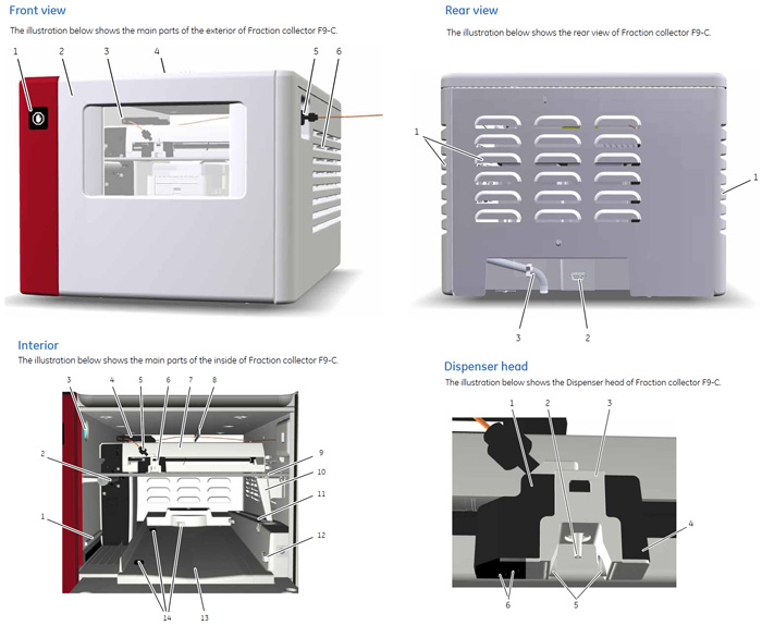
Front view
| Part | Description |
|---|---|
| 1 | Fractionation indicator Symbol indicating that fractionation is ongoing. Do not open the door while the indicator is lit. |
| 2 | Door |
| 3 | Window |
| 4 | Door handle |
| 5 | Tubing connector for outlet valve tubing |
| 6 | Vents |
Rear view
| Part | Description |
|---|---|
| 1 | Vents |
| 2 | UniNet-9 D-type connector (for communication and power supply) |
| 3 | Waste tube |
Interior
| Part | Description |
|---|---|
| 1 | Fractionation arm guide rail |
| 2 | Fractionation arm main rail |
| 3 | Lamp |
| 4 | Tubing guide |
| 5 | Tubing connection |
| 6 | Dispenser head |
| 7 | Fractionation arm |
| 8 | Tubing guide |
| 9 | Height exclusion bar |
| 10 | Waste funnel |
| 11 | Waste tube |
| 12 | Tray catch |
| 13 | Waste groove, in case of overflow |
| 14 | Tray guides |
Dispenser head
| Part | Description |
|---|---|
| 1 | Dispenser head |
| 2 | Nozzle |
| 3 | Dispenser head cover |
| 4 | Accumulator (back part of Dispenser head) |
| 5 | Drop sync sensor |
| 6 | Type code reader |
| # | Product Name | Product Code | Price | |
|---|---|---|---|---|
| UNIPLATE Collection and Analysis Microplate, 24-well, 10 ml, natural polypropylene, round well bottom | 28420867 | 343.00 USD |
Add to cart
|
|
| UNIPLATE Collection and Analysis Microplate, 96-well, 2 ml, natural polypropylene, round well bottom | 28420869 | 273.00 USD |
Add to cart
|
|
| UNIPLATE Collection and Analysis Microplate, 48-well, 5 ml, natural polypropylene, rectangular well, flat bottom | 28420874 | 350.00 USD |
Add to cart
|
|
| Cassette tray | 28954209 | 310.00 USD |
Add to cart
|
|
| Cassette for fraction collection in deep-well plate | 28954212 | 194.58 USD |
Add to cart
|
|
| Cassette for 50 ml tubes | 28956402 | 197.68 USD |
Add to cart
|
|
| Cassette, for 15 ml tubes | 28956404 | 197.68 USD |
Add to cart
|
|
| Cassette for fraction collection in 8 mL tubes | 28956425 | 198.72 USD |
Add to cart
|
|
| Cassette, for 3 ml tubes | 28956427 | 198.72 USD |
Add to cart
|
|
| Rack, for 50 ml tubes | 28980319 | 774.00 USD |
Add to cart
|
|
| Rack for fraction collection in 250 mL bottles | 28981873 | 1,660.00 USD |
Add to cart
|
|
| Fraction Collector F9-C | 29027743 | 12,500.00 USD |
Add to cart
|
|
| Cable 2.5m UniNet-9 D-type | 29032425 | 140.76 USD |
Add to cart
|
| # | Product Name | Product Code | Price | |
|---|---|---|---|---|
| Superloop Complete, 150 ml, M6 fitting | 18102385 | 1,701.00 USD |
Add to cart
|
|
| Injection Kit, INV-907 | 18111089 | 630.00 USD |
Add to cart
|
|
| Superloop, 1/16" fittings (ÄKTAdesign), 50 ml | 18111382 | 1,362.00 USD |
Add to cart
|
|
| Sample loop 100 µl | 18111398 | 187.33 USD |
Add to cart
|
|
| Sample loop 500 µl | 18111399 | 243.00 USD |
Add to cart
|
|
| Sample loop 1 ml | 18111401 | 205.00 USD |
Add to cart
|
|
| Sample Loop 2.0 ml | 18111402 | 304.00 USD |
Add to cart
|
|
| Sample loop, 10 µl | 18112039 | 80.73 USD |
Add to cart
|
|
| Fill Port, INV-907 | 18112766 | 266.00 USD |
Add to cart
|
|
| Sample loop, FEP 10 ml | 18116124 | 215.00 USD |
Add to cart
|
|
| Superloop, M6 fitting, 10 ml | 19758501 | 1,869.00 USD |
Add to cart
|
|
| Connector 1/16" Male/Luer Female | 28985812 | 982.97 USD |
Add to cart
|
Up to four external air sensors can be added to ÄKTA pure, and there are two different versions to choose from. They differ in internal diameter and optimal position on the instrument.
The air sensors can be attached to the instrument using the rails and holders. No dummy modules need to be removed.
In addition to be used for preventing air from entering the system, the external air sensors can be used together with System pump A to load the entire sample volume.
Air sensor L9-1.5
L9-1.5 has a 1.5 mm inner diameter and is designed for i.d. 1.6 mm FEP tubing at the low pressure side before pumps. It is installed in the flow path before the system pumps and is used to prevent air entering the valve.
Air sensor L9-1.2
L9-1.2 has a 1.2 mm inner diameter and is designed for o.d. 1/16" tubing at the high pressure side after the pumps. It is installed after the injection valve and is used to prevent air entering the column.
Tubing connections
Air sensor L9-1.5
| Connection between | Tubing | Connector |
|---|---|---|
| L9-1.5 and inlet valves | FEP, o.d. 1/8", 1.6 mm | Tubing connector, 5/16" + Ferrule (yellow), 1/8" |
Note: When the air sensor is installed before System pump A, use tubing with a minimum length of 18 cm between the valve located before System pump A and the external air sensor when loading the sample at maximum flow rate, to be sure that air does not reach System pump A. Shorter tubing can be used at lower flow rates.
Air sensor L9-1.2
| Connection between | Tubing | Connector |
|---|---|---|
| V9-Inj and L9-1.2 | PEEK, o.d. 1/16" | Fingertight connector 1/16" |
| L9-1.2 and V9-C/V9-Cs/the connected column | PEEK, o.d. 1/16" | Fingertight connector 1/16" |
| # | Product Name | Product Code | Price | |
|---|---|---|---|---|
| 1 | Air Sensor L9-1.2 mm | 28956502 | 2,392.00 USD |
Add to cart
|
| 2 | Air Sensor L9-1.5 mm | 28956500 | 2,580.00 USD |
Add to cart
|
Illustration of Fraction collector F9-R, connector panel, base unit and delivery arm.
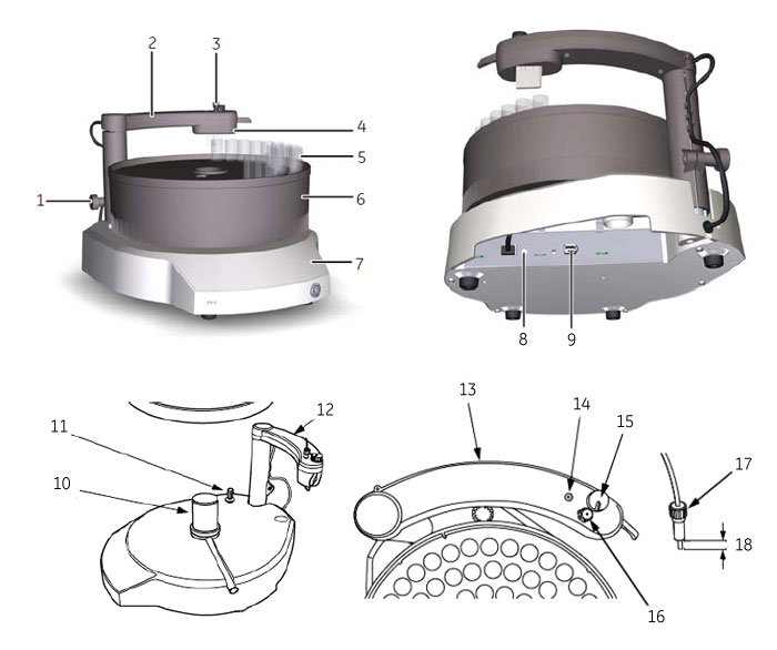
| Part | Function |
|---|---|
| 1 | Lock knob |
| 2 | Delivery arm |
| 3 | Tubing connector |
| 4 | Tube sensor |
| 5 | Collection tubes |
| 6 | Tube rack |
| 7 | Base unit |
| 8 | Node switch |
| 9 | UniNet-9 communication and power supply |
| 10 | Central spindle |
| 11 | Drive sleeve |
| 12 | Delivery arm |
| 13 | Delivery arm |
| 14 | Tube adjustment cavity |
| 15 | Sensor control |
| 16 | Tubing holder |
| 17 | Tubing holder nut |
| 18 | Exposed tubing end length |
| # | Product Name | Product Code | Price | |
|---|---|---|---|---|
| Tube Rack 40 × 30 mm, bowl, tube support, holder and guide | 18112467 | 609.00 USD |
Add to cart
|
|
| Tube Holder and Guide, 40 × 30 mm | 18112468 | 520.00 USD |
Add to cart
|
|
| Tube Rack Complete, 95 × 10–18 mm | 18305003 | 681.00 USD |
Add to cart
|
|
| Bowl | 18305103 | 205.00 USD |
Add to cart
|
|
| Tube Support | 18305402 | 154.21 USD |
Add to cart
|
|
| Tubing Holder | 18646401 | 99.36 USD |
Add to cart
|
|
| Drive sleeve | 19606702 | 133.07 USD |
Add to cart
|
|
| Tube Holder and Guide, 175 × 12 mm | 19724202 | 419.00 USD |
Add to cart
|
|
| Tube Rack 175 × 12 mm, bowl, tube support, holder and guide | 19868403 | 494.00 USD |
Add to cart
|
|
| Tube Holder and Guide, 95 × 10–18 mm | 19868902 | 275.00 USD |
Add to cart
|
|
| Fraction Collector F9-R | 29011362 | 4,270.00 USD |
Add to cart
|
The illustration below shows the location, together with a detailed view of Mixer M9.
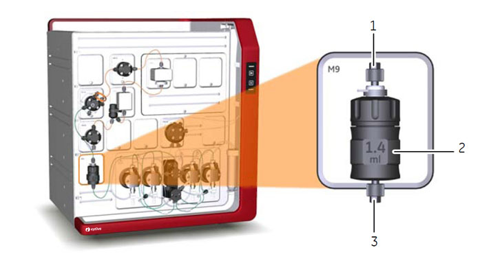
| Part | Description |
|---|---|
| 1 | Outlet |
| 2 | Mixer chamber |
| 3 | Inlet |
Select Mixer chamber
To obtain a homogeneous buffer composition, it is important to use a Mixer chamber suitable for the flow rate of the method. The tables below show what Mixer chambers to use in ÄKTA pure at different flow rates.
If the liquids are difficult to mix, use a larger Mixer chamber to achieve optimal mixing. However, note that a larger Mixer chamber distorts and delays the gradient.
Three different Mixer chambers are available for ÄKTA pure 25. Their volumes are: 0.6 ml, 1.4 ml (mounted at delivery), and 5 ml.
| Mixer chamber volume [ml] | Flow rate [ml/min], Binary gradient |
|---|---|
| 0.6 | 0.1-5 |
| 1.4 | 0.5-10 |
| 5 | 5-25 |
CAUTION
Risk of explosion. Do not use Mixer chamber 15 ml with an ÄKTA pure 25 configuration.
The maximum pressure for Mixer chamber 15 ml is 5 MPa.
Four different Mixer chambers are available for ÄKTA pure 150. Their volumes are: 0.6 ml, 1.4 ml
(mounted at delivery), 5 ml (included in delivery), and 15 ml.
| Mixer chamber volume [ml] | Flow rate [ml/min], Binary gradient |
|---|---|
| 0.6 | 0.5-5 |
| 1.4 | 0.5-15 |
| 5 | 2-50 |
| 15 | 15-150 |
Note: At low flow rates (below 0.2 ml/min) a gradient of sufficient quality may be achieved with the mixer bypassed.
Note: For the highest flow rates, use the 5 ml mixer for ÄKTA pure 25 and the 15 ml mixer for ÄKTA pure 150. The larger chamber volume minimizes potential pump disturbances.
Note: The 1.4 ml mixer might work up to 25 ml/min provided that the buffers are easily mixed.
Note: O-ring 13.1 x 1.6 mm 28-9535-45 is for use with Mixer chamber 0.6, 1.4 and 5 ml.
Note: O-ring 22.1 x 1.6 mm 28-9818-57 is for use with Mixer chamber 15 ml.
Note: O-ring 13.1 x 1.6 mm 29-0113-26 (high resistant) can be used as an alternative to 29-9535-45.
| # | Product Name | Product Code | Price | |
|---|---|---|---|---|
| Online filter kit | 18102711 | 144.90 USD |
Add to cart
|
|
| O-ring 13.1x1.6 mm | 28953545 | 86.95 USD |
Add to cart
|
|
| Mixer chamber 0.6 ml | 28956186 | 1,355.00 USD |
Add to cart
|
|
| Mixer chamber 1.4 ml | 28956225 | 1,370.00 USD |
Add to cart
|
|
| Mixer chamber 5 ml | 28956246 | 1,370.00 USD |
Add to cart
|
|
| Mixer chamber 15 ml | 28980309 | 1,969.00 USD |
Add to cart
|
|
| O-ring 22.1 x 1.6 mm | 28981857 | 139.72 USD |
Add to cart
|
|
| O-ring 13.1 x 1.6 mm High resistance | 29011326 | 205.00 USD |
Add to cart
|
ÄKTA pure protein purification system: Sample automation
| # | Product Name | Product Code | Price | |
|---|---|---|---|---|
| Sample tubing kit for 7 inlets, i.d. 0.75 mm | 28957217 | 274.00 USD |
Add to cart
|
|
| Mixer Valve Kit V9-M | 29011354 | 3,399.00 USD |
Add to cart
|
|
| Sample Pump S9 | 29027745 | 8,696.00 USD |
Add to cart
|
|
| Sample Inlet Valve Kit V9-IS | 29027746 | 6,516.00 USD |
Add to cart
|
|
| Cable 2.5m UniNet-9 D-type | 29032425 | 140.76 USD |
Add to cart
|
|
| Tubing Kit i.d. 1.0 mm | 29032426 | 1,161.00 USD |
Add to cart
|
|
| Tubing kit for Sample Inlet Valve V9-IS | 29035331 | 307.00 USD |
Add to cart
|
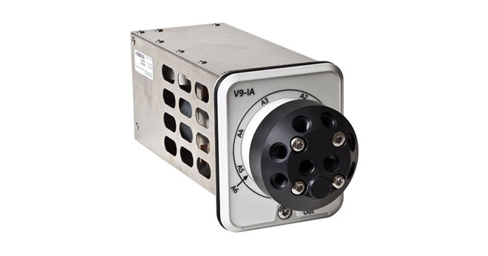
Location and illustration of Conductivity monitor C9n
The illustration below shows the recommended location of Conductivity monitor C9n, together with a detailed view of the monitor. The monitor is labelled C9.
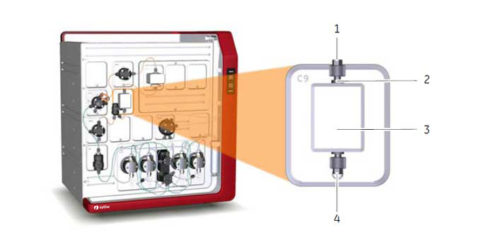
| Part | Description |
|---|---|
| 1 | Inlet |
| 2 | Conductivity flow cell |
| 3 | Conductivity monitor C9n |
| 4 | Outlet |
| # | Product Name | Product Code | Price | |
|---|---|---|---|---|
| Conductivity monitor (C9n) | 29011363 | 2,909.00 USD |
Add to cart
|
Location and illustration of UV monitor U9-M, UV monitor U9-T, and UV monitor U9-L
The illustration below shows the location of UV monitor U9-M with a detailed view of the monitor unit and detector. The monitor unit is labelled U9-M and the detector U9-D.
Note: When UV monitor U9-M is used, the entire Multi-module panel shown in the illustration is replaced by U9-M.
The illustration below also shows the recommended location of UV monitor U9-L and UV monitor U9-T, together with a detailed view of the monitor .monitor. The UV monitors U9-L and U9-T require that the multi-module panel is installed.
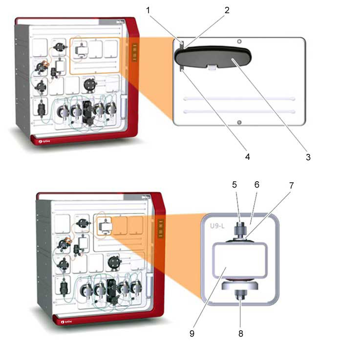
| Part | Description |
|---|---|
| 1 | Inlet |
| 2 | UV flow cell. Three different path lengths are available: 0.5 mm, 2 mm (default) and 10 mm |
| 3 | UV detector |
| 4 | Outlet |
| 5 | Inlet |
| 6 | UV monitor U9-L and UV monitor U9-T |
| 7 | UV flow cell. Two different path lengths are available: 2 mm (default) and 5 mm |
| 8 | Outlet |
| 9 | UV detector |
Function of UV monitor U9-L
The UV monitor U9-L measures the UV absorbance at the fixed wavelength of 280 nm. It is not possible to vary the wavelength, or turn on or off the U9-L monitor. This is therefore not shown in the Phase Properties pane in Method Editor.
For information on how to install UV monitor U9-L, please refer to Section 4.10 Install UV monitor U9-L, in the system handbook.
Function of UV monitor U9-T
The UV monitor U9-T measures the UV absorbance at the fixed wavelengths of 260 and 280 nm. It is not possible to vary the wavelength or turn on or off the U9-T monitor on and off. This is therefore not shown in the Phase Properties pane in Method Editor.
For information on how to install UV monitor U9-T, please refer to Section 4.10 Install UV monitor U9-T, in the system handbook.
Using two UV monitors
The UV monitor U9-T module has two configurations: UV monitor U9-T and UV monitor U9-T, 2nd. The configuration is defined by the module's Node ID. It is possible to use two UV monitors for ÄKTA pure™ in the following combinations:
• UV monitor U9-M together with UV monitor U9-L and or U9-T, 2nd
• UV monitor U9-L together with UV monitor U9-L, 2nd
UV monitor U9-T, 2nd can be located anywhere in the flow path and is therefore shown in the Process Picture as a component without a fixed place. This means that it is possible to place U9-T, 2nd before the other UV monitor in the flow path.
Note: If U9-T, 2nd is placed on the high-pressure side of the column, pressure limits have tomust be considered.
| # | Product Name | Product Code | Price | |
|---|---|---|---|---|
| UV flow cell, 5 mm, for U9-L | 18112824 | 2,622.00 USD |
Add to cart
|
|
| UV flow cell, 10 mm, for U9-M | 28956378 | 2,375.00 USD |
Add to cart
|
|
| UV flow cell, 2 mm, for U9-M | 28979380 | 3,530.00 USD |
Add to cart
|
|
| UV flow cell, 0.5 mm, for U9-M | 28979386 | 3,667.00 USD |
Add to cart
|
|
| UV flow cell, 2 mm, for U9-L | 29011325 | 2,835.00 USD |
Add to cart
|
|
| UV Monitor U9-L | 29011360 | 6,564.00 USD |
Add to cart
|
|
| UV monitor U9-T | 29710522 | 12,600.00 USD |
Add to cart
|
The modular design allows the user to customize ÄKTA pure in multiple ways. The system is always delivered with the core modules of the selected configuration, but one or more optional modules may be added to the flow path.
The table below contains information on the core modules and the optional modules of ÄKTA pure 25 and ÄKTA pure 150.
The valves for ÄKTA pure 25 and ÄKTA pure 150 are compatible with both systems but for the best performance the specific valve type should be used.
Note: All valve kits include the necessary tubing.
| Module | Label in ÄKTA pure 25 | Label in ÄKTA pure 150 |
|---|---|---|
| System pump A | P9 A | P9H A |
| System pump B | P9 B | P9H B |
| Pressure monitor | R9 | R9 |
| Mixer | M9 | M9 |
| Injection valve | V9-Inj | V9H-Inj |
| Inlet valve A | V9-IA | V9H-IA |
| Inlet valve B | V9-IB | V9H-IB |
| Inlet valve AB | V9-IAB | V9H-IAB |
| Inlet valve IX | V9-IX | V9H-IX |
| Sample inlet valve | V9-IS | V9H-IS |
| Mixer valve | V9-M | V9H-M |
| Loop valve | V9-L | V9H-L |
| Column valves |
V9-C V9-Cs |
V9H-C V9H-Cs |
| pH valve | V9-pH | V9H-pH |
| Outlet valves |
V9-O V9-Os |
V9H-O V9H-Os |
| Versatile valve | V9-V | V9H-V |
| UV monitors |
U9-L U9-M |
U9-L U9-M |
| Conductivity monitor | C9 | C9 |
| External air sensor |
L9-1.5 L9-1.2 |
L9-1.5 L9-1.2 |
| Fraction collectors |
F9-C F9-R |
F9-C F9-R |
| I/O box | E9 | E9 |
| Sample pump | S9 | S9H |
| # | Product Name | Product Code | Price | |
|---|---|---|---|---|
| Injection Valve, V9-Inj | 28956514 | 4,069.00 USD |
Add to cart
|
|
| Inlet Valve V9-X1 | 28957227 | 4,454.00 USD |
Add to cart
|
|
| Inlet Valve V9-X2 | 28957234 | 4,464.00 USD |
Add to cart
|
|
| Inlet Valve V9H-X1 | 28979326 | 4,398.00 USD |
Add to cart
|
|
| Inlet Valve V9H-X2 | 28979328 | 4,398.00 USD |
Add to cart
|
|
| Versatile valve V9-V | 29011353 | 3,224.00 USD |
Add to cart
|
|
| Mixer Valve Kit V9-M | 29011354 | 3,399.00 USD |
Add to cart
|
|
| Column Valve V9-Cs | 29011355 | 3,701.00 USD |
Add to cart
|
|
| Outlet Valve Kit V9-Os | 29011356 | 2,483.00 USD |
Add to cart
|
|
| Inlet Valve Kit V9-IAB | 29011357 | 3,210.00 USD |
Add to cart
|
|
| Loop valve V9-L | 29011358 | 6,306.00 USD |
Add to cart
|
|
| pH Valve Kit V9-pH | 29011359 | 3,250.00 USD |
Add to cart
|
|
| Column Valve kit V9-C | 29011367 | 8,734.00 USD |
Add to cart
|
|
| Outlet valve kit V9-O | 29012261 | 4,295.00 USD |
Add to cart
|
|
| Inlet Valve Kit V9-IA | 29012263 | 6,516.00 USD |
Add to cart
|
|
| Inlet Valve Kit V9-IB | 29012370 | 6,516.00 USD |
Add to cart
|
|
| Sample Inlet Valve Kit V9-IS | 29027746 | 6,516.00 USD |
Add to cart
|
|
| Sample Inlet Valve Kit V9H-IS | 29050943 | 6,516.00 USD |
Add to cart
|
|
| Inlet Valve Kit V9H-IA | 29050945 | 6,516.00 USD |
Add to cart
|
|
| Inlet Valve Kit V9H-IB | 29050946 | 6,516.00 USD |
Add to cart
|
|
| Outlet Valve Kit V9H-O | 29050949 | 4,295.00 USD |
Add to cart
|
|
| Column Valve Kit V9H-C | 29050951 | 8,734.00 USD |
Add to cart
|
|
| pH Valve Kit V9H-pH | 29051684 | 3,256.00 USD |
Add to cart
|
|
| Inlet Valve Kit V9H-IAB | 29089652 | 3,147.00 USD |
Add to cart
|
|
| Loop valve kit V9H-L | 29090689 | 6,306.00 USD |
Add to cart
|
|
| Versatile valve V9H-V | 29090691 | 3,159.00 USD |
Add to cart
|
|
| Mixer Valve Kit V9H-M | 29090692 | 3,339.00 USD |
Add to cart
|
|
| Column Valve V9H-Cs | 29090693 | 3,629.00 USD |
Add to cart
|
|
| Outlet Valve Kit V9H-Os | 29090694 | 2,439.00 USD |
Add to cart
|
Location and illustration of the pH monitor
The illustration below shows the location of the pH flow cell and a pH electrode installed in the pH valve.
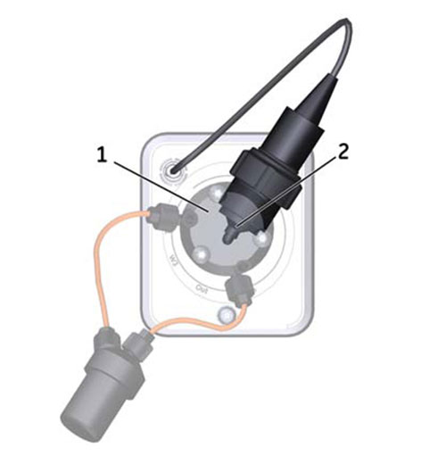
| Part | Description |
|---|---|
| 1 | pH flow cell |
| 2 | pH electrode |
| # | Product Name | Product Code | Price | |
|---|---|---|---|---|
| 1 | O-ring 5.3 x 2.4 mm | 28956497 | 159.39 USD |
Add to cart
|
| 2 | pH electrode | 29387193 | 828.00 USD |
Add to cart
|
Flow path schemes
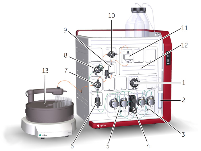
The illustration below shows the flow path for a typical system configuration. The individual instrument modules are presented in the table below. The configuration of the system is defined by the user.
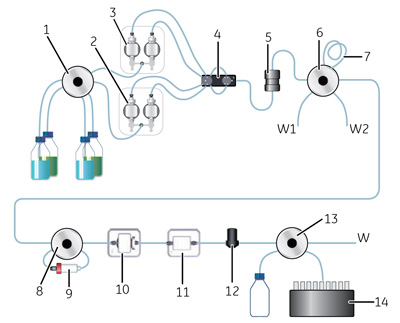
| Part | Description |
|---|---|
| 1 | Inlet valve V9-IAB |
| 2 | System pump B |
| 3 | System pump A |
| 4 | Pressure monitor R9 |
| 5 | Mixer M9 |
| 6 | Injection valve V9-Inj |
| 7 | Capillary loop or Superloop |
| 8 | Column valve V9-Cs |
| 9 | Column |
| 10 | UV monitor U9-L |
| 11 | Conductivity monitor C9n |
| 12 | Flow restrictor |
| 13 | Outlet valve V9-Os |
| 14 | Fraction collector F9-R |
| W, W1, W2 | Waste |
Tubing types
The table below shows the tubing types used in ÄKTA pure.
| Description | Color | Scope of use |
|---|---|---|
| PEEK, o.d. 1/16", i.d. 0.25 mm | Blue | Reference capillary 1 and Tubing Kit 0.25 |
| PEEK, o.d. 1/16", i.d. 0.50 mm | Orange | High pressure tubing |
| PEEK, o.d. 1/16", i.d. 0.75 mm | Green | High pressure tubing |
| FEP, o.d. 1/8", i.d. 1.6 mm | Transparent | Inlet tubing |
| ETFE, o.d. 1/16", i.d. 1.0 mm | Transparent | Outlet and waste tubing |
| Silicon, o.d. 12 mm, i.d. 8 mm | Transparent | Waste tubing from Buffer tray |
Note: Many different sizes/types of tubing can be connected to a chromatography system. Tubing with a smaller inner diameter (i.d.) holds less delay volume and will therefore generate less dilution of the protein peak. Narrow tubing, however, increases the system pressure, especially when running at high flow rates. The tubing used should match the application needs. See Recommended tubing kits, on page 467 in the System Handbook for more information.
Tubing connectors
The table below shows the tubing connectors used in ÄKTA pure.
| Description | Use with tubing... |
|---|---|
| Fingertight connector, 1/16" | • PEEK, o.d. 1/16", i.d. 0.25 mm • PEEK, o.d. 1/16", i.d. 0.50 mm • PEEK, o.d. 1/16", i.d. 0.75 mm • ETFE, o.d. 1/16", i.d. 1 mm |
| Tubing connector 5/16" Ferrule (yellow), 1/8" |
FEP, o.d. 1/8", i.d. 1.6 mm |
Other connectors
The table below shows other connectors used in ÄKTA pure.
| Description | Scope of use |
|---|---|
| Stop plug 1/16" | Stop plug for valve parts |
| Luer female | Syringe connector for pH valve and Injection valve |
Tubing labels
The illustration below shows the tubing labels for for a typical system configuration.
Inlet tubing
The table below shows the labels, diameters, and standard lengths of the inlet tubing.
| Label | Description | Tubing | Length (mm) |
|---|---|---|---|
| A1-A2 and B1-B2 |
Inlets to Inlet valve AB | FEP, o.d. 1/8", i.d. 1.6 mm | 1500 |
| A1-A7 | Inlets to Inlet valve A | FEP, o.d. 1/8", i.d. 1.6 mm | 1500 |
| B1-B7 | Inlets to Inlet valve B | FEP, o.d. 1/8", i.d. 1.6 mm | 1500 |
| InA | FromInlet valve A or Inlet valve AB to System pump A | FEP, o.d. 1/8", i.d. 1.6 mm | 220 |
| InB | FromInlet valve B or Inlet valve AB to System pump B | FEP, o.d. 1/8", i.d. 1.6 mm | 220 |
High pressure tubing
The table below shows the labels, diameters, and standard lengths of the high pressure tubing.
| Label | Description | Tubing | Length (mm) |
|---|---|---|---|
| 1A1 | System pump A left to Restrictor A | PEEK, o.d. 1/16", i.d. 0.75 mm | 340 |
| 1A2 | System pump A right to Restrictor A | PEEK, o.d. 1/16", i.d. 0.75 mm | 340 |
| 2A | Restrictor A to Pressure monitor | PEEK, o.d. 1/16", i.d. 0.75 mm | 115 |
| 1B1 | System pump B left to Restrictor B | PEEK, o.d. 1/16", i.d. 0.75 mm | 340 |
| 1B2 | System pump B right to Restrictor B | PEEK, o.d. 1/16", i.d. 0.75 mm | 340 |
| 2B | Restrictor B to Pressure monitor | PEEK, o.d. 1/16", i.d. 0.75 mm | 115 |
| 3 | Pressure monitor to Mixer | PEEK, o.d. 1/16", i.d. 0.75 mm | 400 |
| 4 | Mixer to Injection valve | PEEK, o.d. 1/16", i.d. 0.75 mm | 200 |
| 5 | Injection valve to Column valve | PEEK, o.d. 1/16", i.d. 0.75 mm | 160 |
| 6 | Column valve to UV monitor | PEEK, o.d. 1/16", i.d. 0.75 mm | 160 |
| 7 | UV monitor to Conductivy monitor | PEEK, o.d. 1/16", i.d. 0.75 mm | 170 |
| 8 | Conductivity monitor to Flow restrictor | PEEK, o.d. 1/16", i.d. 0.75 mm | 95 |
| 9 | Flow restrictor to Outlet valve | PEEK, o.d. 1/16", i.d. 0.75 mm | 135 |
| Frac | Outlet valve to Fraction collector | PEEK, o.d. 1/16", i.d. 0.75 mm | 400 |
Reference capillaries
The table below shows the labels, diameters, and standard lengths of the reference capillary. The capillary is used during the System performance tests.
| Label | Description | Tubing | Length (mm) |
|---|---|---|---|
| Ref 1 | Reference capillary | PEEK, o.d. 1/16", i.d. 0.25 mm | 400 |
Outlet tubing
The table below shows the labels, diameters, and standard lengths of the outlet tubing.
The tubing is not mounted on delivery.
| Label | Description | Tubing | Length (mm) |
|---|---|---|---|
| Out1-Out 10 | Outlets from Outlet valve V9-O and Outlet valve V9-Os | ETFE, o.d. 1/8", i.d. 1 mm | 1500 |
Waste tubing
The table below shows the labels, diameters, and standard lengths of the waste tubing. The waste tubing is mounted on delivery.
| Label | Description | Tubing | Length (mm) |
|---|---|---|---|
| W1 | System pump waste | ETFE, o.d. 1/16", i.d. 1.0 mm | 1500 |
| W2 | Sample pump waste | ETFE, o.d. 1/16", i.d. 1.0 mm | 1500 |
| W3 | pH valve waste | ETFE, o.d. 1/16", i.d. 1.0 mm | 1500 |
| W | System waste | ETFE, o.d. 1/16", i.d. 1.0 mm | 1500 |
| N/A | Top tray waste | Silicon, o.d. 12 mm, i.d. 8 mm | 1500 |
Troubleshooting
Find solutions to product related issues. For unlisted issues please contact local Cytiva service representation.
Mixer valve
Issues related to the Mixer valve
| Possible cause | Suggested remedy |
|---|---|
Hardware error |
Switch off the instrument and wait until the temperature has decreased. Restart the instrument. If this error is recurrent, generate a System error report and contact Service. |
Hot surroundings |
Decrease the room temperature. Maximum operating temperature is 35°C. |
The air intake on the rear or on the right side of the instrument is covered |
Make sure that none of the air intakes on the instrument are covered. |
| Possible cause | Suggested remedy |
|---|---|
Wrong Node ID |
Check the module's Node ID. If necessary, change the Node ID. See Section 4.4 Install Mixer valve V9-M, in the System Handbook. |
The cable between the Mixer valve and the ICU is not connected |
Remove the valve and make sure that the cable is connected. |
Outlet valve
Issues related to the Outlet valve
| Possible cause | Suggested remedy |
|---|---|
Hardware error |
Switch off the instrument and wait until the temperature has decreased. Restart the instrument. If this error is recurrent, generate a System error report and contact Service. |
Hot surroundings |
Decrease the room temperature. Maximum operating temperature is 35°C. |
The air intake on the rear or on the left side of the instrument is covered |
Make sure that none of the air intakes on the instrument are covered. |
| Possible cause | Suggested remedy |
|---|---|
Wrong Node ID |
Check the module's Node ID. If necessary, change the Node ID. See Section4.9 Install outlet valve, on page171 in the system handbook. |
The cable between the Outlet valve and the ICU is not connected |
Remove the valve and make sure that the cable is connected. See Section 4.9 Install outlet valve, on page 171 in the system handbook. |
Instrument communication
Issues related to Instrument communication
| Possible cause | Suggested remedy |
|---|---|
Warning messages in UNICORN: (Warning) Gate (12): Internal instrument error. |
1 Switch off the instrument. Restart the system only and click OK. |
| Possible cause | Suggested remedy |
|---|---|
Two or several modules have the same Node ID. |
1 Switch off the instrument. |
| Possible cause | Suggested remedy |
|---|---|
The module is not functioning properly. |
1 In the displayed dialog in UNICORN, select the option Restart the system only and click OK. |
| Possible cause | Suggested remedy |
|---|---|
The UNICORN client has lost connection to the instrument server during a temporary overload of the processor. |
Restart the UNICORN client to regain control. The run continues and no data will be lost. |
| Possible cause | Suggested remedy |
|---|---|
A UniNet-9 connector is not plugged. |
Check that all UniNet-9 connectors that are not in use are plugged. |
A cable to a module (including dummy modules) is not connected. |
1 Switch off the instrument. |
Cabinet
Issues related to the cabinet
| Possible cause | Suggested remedy |
|---|---|
The waste tubing from the Buffer tray is loose |
Contact Service. |
| Possible cause | Suggested remedy |
|---|---|
Hot surroundings |
Decrease the room temperature. Maximum operating temperature is 35°C. |
Broken fans |
Contact Service. |
The air intake on the back or on the left side of the instrument is covered |
Make sure that none of the air intakes on the instrument are covered. |
General hardware: All modules
Issues related to general hardware: All modules
| Possible cause | Suggested remedy |
|---|---|
The Node ID for one or more of the modules is incorrect |
Check Node ID and change the Node ID according to Node ID, on page 465 in the system handbook. |
| Possible cause | Suggested remedy |
|---|---|
The Node ID for one or more of the modules is incorrect, for example an Inlet valve A2 has the same Node ID as Inlet valve A. The instrument then considers them to have the same identity. |
Remove Inlet valve A2 and change the Node ID. |
Two similar modules have been added to the instrument, for example two Inlet valve A |
Remove one of the modules with the same Node ID. |
The cable between a module and the ICU is not connected |
Remove the module and make sure that the cable is connected. |
Superloop
Issues related to the Superloop
| Possible cause | Suggested remedy |
|---|---|
The Superloop is filled to the max. Pressure is not released anywhere |
Manually turn Injection valve to Manual load position. |
I/O-box E9
Issues related to I/O-box E9
| Possible cause | Suggested remedy |
|---|---|
Analog Out does not generate expected voltage |
Contact Service. |
| Possible cause | Suggested remedy |
|---|---|
Analog In is not calibrated |
Contact Service. |
| Possible cause | Suggested remedy |
|---|---|
Too long cable between the external equipment and E9 |
Use as short cable as possible. Use shielded cable. Connect the cable shield to the D-sub connector’s shield. |
| Possible cause | Suggested remedy |
|---|---|
Digital Out connection error |
Make sure that Digital Out is connected correctly, earth to earth etc. |
Auto-zero on the wrong level |
Reset Auto-zero. |
| Possible cause | Suggested remedy |
|---|---|
Cables incorrectly connected |
Make sure that the cables are connected correctly, earth to earth etc. To isolate the problem: 1 Connect Digital Out (e.g. pin 6) to Digital In (pin 1,2,3, or 4).
|
| Possible cause | Suggested remedy |
|---|---|
Digital Out connections switched |
Check that the digital Out cables are correctly connected, earth to earth etc. |
| Possible cause | Suggested remedy |
|---|---|
Cables incorrectly connected |
Make sure that the cables are connected correctly, earth to earth etc. |
| Possible cause | Suggested remedy |
|---|---|
Wrong Node ID |
Make sure that the Node ID is (00) for the primary box, and (01) for a potential secondary box. |
| Possible cause | Suggested remedy |
|---|---|
Hot surroundings |
Decrease the room temperature. Maximum operating temperature is 35 C. |
Pumps
Issues related to the Pumps
| Possible cause | Suggested remedy |
|---|---|
Too high I factor in the Constant pressure flow parameters instruction |
In the Manual Instructions dialog, decrease the I factor of the Constant pressure flow parameters instruction. |
| Possible cause | Suggested remedy |
|---|---|
Too high I factor in the Pressure control parameters instruction |
In the Manual Instructions dialog, decrease the I factor of the Pressure control parameters instruction. |
| Possible cause | Suggested remedy |
|---|---|
Too low I factor in the Constant pressure flow parameters instruction |
In the Manual Instructions dialog, increase the I factor of the Constant pressure flow parameters instruction. |
| Possible cause | Suggested remedy |
|---|---|
Too low I factor in the Pressure control parameters instruction |
In the Manual Instructions dialog, increase the I factor of the Pressure control parameters instruction. |
| Possible cause | Suggested remedy |
|---|---|
Blocked pump restrictor |
Contact Service. |
| Possible cause | Suggested remedy |
|---|---|
The flow path is blocked |
Remove obstructions in the flow path. For example, remove stop plugs and replace constricted tubing. |
| Possible cause | Suggested remedy |
|---|---|
Clogged inline filter |
Replace the inline filter, see Section 7.3.2 Replace the inline filter, on page 312 in the system handbook. |
| Possible cause | Suggested remedy |
|---|---|
The flow is too high |
Lower the flow. |
The parameter selected for pressure control is not the most appropriate one |
The pressure control is based on either the Pre column pressure or the Delta column pressure. To change the parameter for pressure control, select Pre column pressure or Delta column pressure from the Pressure control drop-down list in the Instruction box of the instruction of interest. |
| Possible cause | Suggested remedy |
|---|---|
The pressure has increased due to increased viscosity |
The viscosity increases in cold room. Lower the flow when performing runs in a cold room. |
| Possible cause | Suggested remedy |
|---|---|
Hardware error |
Switch off the instrument and wait until the temperature has decreased. Restart the instrument. If this error is recurrent, generate a System error report and contact Service. |
Hot surroundings |
Decrease the room temperature. Maximum operating temperature is 35°C. |
The air intake on the rear or on the left side of the instrument is covered |
Make sure that none of the air intakes on the instrument are covered. |
| Possible cause | Suggested remedy |
|---|---|
A fuse in the instrument ICU is broken |
Contact Service. |
The cable between the pump and the ICU is not connected |
Contact Service. |
| Possible cause | Suggested remedy |
|---|---|
• Air trapped in the pump heads |
See Examples of pump pressure curves, on page 427 in the system handbook for examples of pump pressure curves. |
| Possible cause | Suggested remedy |
|---|---|
Leaking connection and/or crystallized material around a connector |
Unscrew the connector and check if it is worn or incorrectly fitted. If so, replace the connector. Gently finger tighten the connector. |
| Possible cause | Suggested remedy |
|---|---|
Bad pump piston seal |
Replace the piston seal and rinse membrane according to Section 7.8.9 Replace pump piston seals of Pump P9, on page 381 in the system handbook. |
Bad pump piston |
If the piston is damaged, replace it according to Section 7.8.10 Replace pump pistons, on page 391 in the system handbook. |
Bad piston spring |
Disassemble the pump head and examine the piston spring. If the spring is corroded, check piston seal and rinse membrane. Make sure that the pump piston rinsing system is always used when working with aqueous buffers containing salt. |
Air in pumps |
Purge the pumps. See Section 5.4 Prime inlets and purge pump heads, on page 217 in the system handbook. |
| Possible cause | Suggested remedy |
|---|---|
Piston seal or rinsing membrane incorrectly fitted or worn |
Replace or reinstall the seal or the membrane. See Section 7.8.9 Replace pump piston seals of Pump P9, on page 381 in the system handbook. |
Instrument control panel
Issues related to the Instrument control panel
| Possible cause | Suggested remedy |
|---|---|
Hardware error |
Switch off the instrument and wait until the temperature has decreased. Restart the instrument. If this error is recurrent, generate a System error report and contact Service. |
Hot surroundings |
Decrease the room temperature. Maximum operating temperature is 35 C. |
The air intake on the rear or on the right side of the instrument is covered. |
Make sure that none of the air intakes of the instrument are covered. |
Versatile valve
Issues related to the Versatile valve
| Possible cause | Suggested remedy |
|---|---|
Hardware error |
Switch off the instrument and wait until the temperature has decreased. Restart the instrument. If this error is recurrent, generate a System error report and contact Service. |
Hot surroundings |
Decrease the room temperature. Maximum operating temperature is 35°C. |
The air intake on the rear or on the right side of the instrument is covered |
Make sure that none of the air intakes on the instrument are covered. |
| Possible cause | Suggested remedy |
|---|---|
Wrong Node ID |
Check the module's Node ID. If necessary, change the Node ID. See Section 4.7 Install Versatile valve V9-V, on page 159 in the system handbook. |
The cable between the Versatile valve and the ICU is not connected |
Remove the valve and make sure that the cable is connected. |
Examples of pump pressure curves
The table below shows some examples of pump system pressure curves obtained when errors have occurred. The examples can be useful in troubleshooting of the System pumps. The System pressure monitor R9 has higher resolution than the other pressure monitors, and is therefore recommended for troubleshooting purposes.
Incident: 30 μl of air enters pump.
Action: Purge pump. See Section 5.4 Prime inlets and purge pump heads, on page 217 in the system handbook.
Incident: A large volume of air enters pump.
Action: Purge pump. See Section 5.4 Prime inlets and purge pump heads, on page 217.
Incident: Blocked outlet check valve
Action: Clean the check valve, See Section 7.6.7 Clean the pump head check valves, on page 343 in the system handbook.
Incident: Inlet check valve is loose.
Action: Tighten the check valve. See Section 7.8.8 Replace the pump head check valves, on page 378 in the system handbook.
Incident: Leaking inlet check valve.
Action: Replace the check valve. See Section 7.8.8 Replace the pump head check valves, on page 378 in the system handbook.
Incident: Leaking outlet check valve.
Actions: Replace the check valve. See Section 7.8.8 Replace the pump head check valves, on page 378 in the system handbook.
Incident: One inlet is blocked,
Action: Clean inlet tubing. For example, perform a System CIP.
Loop valve
Issues related to Loop valve
| Possible cause | Suggested remedy |
|---|---|
Hardware error |
Switch off the instrument and wait until the temperature has decreased. Restart the instrument. If this error is recurrent, generate a System error report and contact Service. |
Hot surroundings |
Decrease the room temperature. Maximum operating temperature is 35°C. |
The air intake on the rear or on the right side of the instrument is covered |
Make sure that none of the air intakes on the instrument are covered. |
| Possible cause | Suggested remedy |
|---|---|
Wrong Node ID |
Check the module's Node ID. If necessary, change the Node ID. See Section 4.5 Install Loop valve V9-L, on page 148 in the system handbook. |
The cable between the Loop valve and the ICU is not connected |
Remove the valve and make sure that the cable is connected. |
Inlet valves
Issues related to Inlet valves.
The Inlet valves include Inlet valve A, Inlet valve B and Inlet valve AB.
| Possible cause | Suggested remedy |
|---|---|
Broken valve |
Replace the valve. See Section 4.3 Install inlet valves, on page 138 in the system handbook. |
| Possible cause | Suggested remedy |
|---|---|
Leaking tubing connectors |
Check the tubing connectors. Tighten or replace the connectors. To order connectors, see Chapter 10 Ordering information, on page 526 in the system handbook. |
| Possible cause | Suggested remedy |
|---|---|
Hardware error |
Generate a System error report and contact Service. |
| Possible cause | Suggested remedy |
|---|---|
Hardware error |
Switch off the instrument and wait until the temperature has decreased. Restart the instrument. If this error is recurrent, generate a System error report and contact Service. |
Hot surroundings |
Decrease the room temperature. Maximum operating temperature is 35°C. |
The air intake on the rear or on the left side of the instrument is covered |
Make sure that none of the air intakes on the instrument are covered. |
| Possible cause | Suggested remedy |
|---|---|
Hardware error |
Restart the instrument with the power switch. If this error is recurrent, generate a System error report and contact Service. |
| Possible cause | Suggested remedy |
|---|---|
Wrong Node ID |
Check the module´s Node ID. If necessary, change the Node ID. See Section4.3 Install inlet valves, on page138 in the system handbook. |
The cable between the Inlet valve and the ICU is not connected |
Remove the valve and make sure that the cable is connected. See Section 4.3 Install inlet valves, on page 138 in the system handbook. |
Fraction collector F9-R
Issues related to Fraction collector F9-R
| Possible cause | Suggested remedy |
|---|---|
Too many fraction collector instructions have been sent |
Wait for a while and try again. |
The fraction volume is too small |
Collect larger fractions. |
The flow rate is too high |
Reduce the flow rate. |
| Possible cause | Suggested remedy |
|---|---|
The fraction collector movement is blocked |
Make sure that the fraction collector can move and is free from obstructions. |
| Possible cause | Suggested remedy |
|---|---|
The tubing is not correctly mounted in the tubing holder nut |
Check that the tubing is correctly mounted, see Section 4.12 Install Fraction collector F9-R, on page 186 in the system handbook. |
Unclean drop sync sensor |
Clean the drop sensor photocell located above the tube sensor with a damp cloth. |
Air in the flow path |
Check the flow path for air. Fill system and purge pumps. If this error is recurrent, generate a System error report and contact service. |
To high flow rate for drop sync |
Decrease the flow rate or disable drop sync. |
| Possible cause | Suggested remedy |
|---|---|
Hardware error |
Switch off the instrument and wait until the temperature has decreased. Restart the instrument. If this error is recurrent, generate a System error report and contact service. |
Hot surroundings |
Decrease the room temperature. Maximum operating temperature is 35 C. |
| Possible cause | Suggested remedy |
|---|---|
Wrong node ID |
Check the Fraction collector's Node ID. If necessary, change the Node ID. See Section 4.12 Install Fraction collector F9-R, on page 186 in the system handbook. |
The cable between the Fraction collector and the ICU is not connected |
Make sure that the cable is connected. |
Injection valve
Issues related to Injection valve
| Possible cause | Suggested remedy |
|---|---|
Hardware error |
Switch off the instrument and wait until the temperature has decreased. Restart the instrument. If this error is recurrent, generate a System error report and contact Service. |
Hot surroundings |
Decrease the room temperature. Maximum operating temperature is 35°C. |
The air intake on the rear or on the left side of the instrument is covered |
Make sure that none of the air intakes on the instrument are covered. |
| Possible cause | Suggested remedy |
|---|---|
Wrong Node ID |
Check the module´s Node ID. If necessary, change the Node ID, see Node ID, on page 465 in the system handbook. |
The cable between the Injection valve and the ICU is not connected |
Remove the valve and make sure that the cable is connected Instruction, on page 203 in the system handbook. |
| Possible cause | Suggested remedy |
|---|---|
Hardware error |
Generate a System error report and contact Service. |
pH monitor and pH valve
Issues related to pH monitor and pH valve
| Possible cause | Suggested remedy |
|---|---|
High pressure in the pH cell |
Decrease the flow rate. |
| Possible cause | Suggested remedy |
|---|---|
Waste tubing is twisted or blocked |
Untwist the tubing. |
| Possible cause | Suggested remedy |
|---|---|
The temperature compensation of the pH monitor is turned off |
Contact Service. |
| Possible cause | Suggested remedy |
|---|---|
Decreasing salt concentration in the electrode membrane due to osmosis to buffer |
Regenerate the pH electrode. Place the electrode in deionized water for 30 minutes followed by 30 minutes in a buffer with pH 4. |
| Possible cause | Suggested remedy |
|---|---|
Wrong mixer size for the used flow rate |
Use the recommended mixer size for the used flow rate |
Bad pH electrode |
Regenerate the pH electrode. Place the electrode in deionized water for 30 minutes followed by 30 minutes in a buffer with pH 4. |
Calibration time out |
Check the connections between pH electrode and pH monitor. |
| Possible cause | Suggested remedy |
|---|---|
Hardware error |
Switch off the instrument and wait until the temperature has decreased. Restart the instrument. If this error is recurrent, generate a System error report and contact Service. |
Hot surroundings |
Decrease the room temperature. Maximum operating temperature is 35°C. |
The air intake on the rear or on the left side of the instrument is covered |
Make sure that none of the air intakes on the instrument are covered. |
| Possible cause | Suggested remedy |
|---|---|
The cable between the pH valve and the ICU is not connected |
Remove the pH valve and make sure that the cable is connected. See Section 4.8 Install pH valve V9-pH, on page 164 in the system handbook. |
Dummy modules
Issues related to Dummy modules
| Possible cause | Suggested remedy |
|---|---|
The cable between the dummy module and the ICU is not connected |
Remove the dummy module and make sure that the cable is connected. |
A dummy module is missing and the position is left empty |
Install the missing dummy module. |
Column valve
Issues related to Column valve
| Possible cause | Suggested remedy |
|---|---|
Hardware error |
Switch off the instrument and wait until the temperature has decreased. Restart the instrument. If this error is recurrent, generate a System error report and contact Service. |
Hot surroundings |
Decrease the room temperature. Maximum operating temperature is 35°C. |
The air intake on the rear or on the left side of the instrument is covered |
Make sure that none of the air intakes on the instrument are covered. |
| Possible cause | Suggested remedy |
|---|---|
Wrong Node ID |
Check the module's Node ID. If necessary, change the Node ID. See Section 4.6 Install column valve, on page 152 in the system handbook. |
The cable between the Column valve and the ICU is not connected |
Remove the valve and make sure that the cable is connected. See Install column valve. |
Fraction collector F9-C
Issues related to Fraction collector F9-C
| Possible cause | Suggested remedy |
|---|---|
The cable between the fraction collector and the ÄKTA pure instrument is not connected |
Generate a System error report and contact Service. |
A fuse in the instrument ICU is broken |
The ICU needs to be changed. Generate a System error report and contact Service. |
| Possible cause | Suggested remedy |
|---|---|
Obstruction inside the fraction collector |
Switch off the instrument and check for obstruction inside the fraction collector. Try to move the fractionation arm by hand. Switch on the instrument. If this error is recurrent, generate a System error report and contact Service. |
| Possible cause | Suggested remedy |
|---|---|
Salt crystals or protein residuals block the accumulator |
Restart the instrument and perform an accumulator wash. |
Mechanical error |
If this error is recurrent, generate a System error report and contact Service. |
| Possible cause | Suggested remedy |
|---|---|
Too many commands are pending in the fraction collector |
The reason could be that too many fraction collector instructions have been sent. Wait for a while and try again. |
| Possible cause | Suggested remedy |
|---|---|
Cassette tray or tube rack is inserted in the wrong direction |
Take it out and insert it in the correct direction. |
Unclean Cassette type code reader |
Clean the dispenser head and its four diode windows using a cloth and a mild cleaning agent or 20% ethanol. See Section 8.6.4 Clean Fraction collector F9-C in the ÄKTA pure System Handbook for more information. |
Unclean Cassette type codes |
Clean the Cassette type codes. See Section 8.6.4 Clean Fraction collector F9-C in the ÄKTA pure System Handbook for more information. If this error is recurrent, set the Fraction collector configuration manually in UNICORN. In System Control, select System:Settings. Navigate to Fraction collector:Cassette configuration and select Manual. |
| Possible cause | Suggested remedy |
|---|---|
The Tray guides in the fractionation chamber are missing |
Replace the Tray guides. See Section 8.6.4 Clean Fraction collector F9-C in the ÄKTA pure System Handbook for more information. |
The Tray catch is broken |
Contact service. |
| Possible cause | Suggested remedy |
|---|---|
Unclean Drop sync sensor diode windows |
Clean the Drop sync sensor diode windows. See Section 8.6.4 Clean Fraction collector F9-C in the ÄKTA pure System Handbook for location of the Drop sync sensor diode windows and cleaning instructions. If this error is recurrent, generate a System error report and contact Service. |
| Possible cause | Suggested remedy |
|---|---|
Liquid spatter in the fraction collector |
Change to another type of tubes or deepwell plates or collect fraction volumes of maximum two thirds of the volume of the tubes. Clean the diode windows of the drop sync sensor more frequently than once a week, using a cloth and a mild cleaning agent or 20% ethanol. |
| Possible cause | Suggested remedy |
|---|---|
Air in the flow path |
If this error is recurrent, generate a System error report and contact Service. Check the flow path for air. Fill system and purge pumps according to Section 6.4.1 System pumps in the ÄKTA pure System Handbook. |
Unclean Drop sync sensor diode windows |
Clean the diode windows of the Drop sync sensor. See Section 8.6.4 Clean Fraction collector F9-C in the ÄKTA pure System Handbook for more information. If this error is recurrent, generate a System error report and contact Service. |
Too high flow rate |
Decrease the flow rate. |
| Possible cause | Suggested remedy |
|---|---|
Air in the flow path |
Check the flow path for air. Fill system and purge pumps according to Section 6.4.1 System pumps in the ÄKTA pure System Handbook. If this error is recurrent, generate a System error report and contact Service. |
Unclean diode windows in the Drop sync sensor |
Clean the diode windows of the Drop sync sensor. See Section 8.6.4 Clean Fraction collector F9-C in the ÄKTA pure System Handbook. If this error is recurrent, generate a System error report and contact Service. |
| Possible cause | Suggested remedy |
|---|---|
Too high flow rate |
Decrease the flow rate. |
Air in the flow path |
Check the flow path for air. Fill system and purge pumps according to Section 6.4.1 System pumps in the ÄKTA pure System Handbook. If this error is recurrent, generate a System error report and contact Service. |
Unclean diode windows in the Drop sync sensor |
Clean the diode windows of the Drop sync sensor. See Section 8.6.4 Clean Fraction collector F9-C in the ÄKTA pure System Handbook. If this error is recurrent, generate a System error report and contact Service. |
| Possible cause | Suggested remedy |
|---|---|
Wrong tube dimensions are used |
Check that the used tubes have the right dimensions. See Fraction collector tubes, section 3.2.3 Cassettes, Cassette tray and racks, in the ÄKTA pure System Handbook. |
QuickRelease function is worn out |
Order a new Cassette. See Chapter 11 in the ÄKTA pure System Handbook for ordering information. |
| Possible cause | Suggested remedy |
|---|---|
Unsupported deep well plate model |
Check that the deep well plates are supported. See Deep well plates, section 3.2.3 Cassettes, Cassette tray and racks, in the ÄKTA pure System Handbook. |
| Possible cause | Suggested remedy |
|---|---|
The Cassette is turned in the wrong direction |
See Prepare and insert the Cassette tray, section 6.7.1 Fraction collector F9-C, in the ÄKTA pure System Handbook for information of how to place the Cassettes. |
Objects or dirt under the Cassette |
Remove the object or dirt. |
| Possible cause | Suggested remedy |
|---|---|
The Tray guides in the fractionation chamber are missing |
Replace the Tray guides. See Section 8.6.4 Clean Fraction collector F9-C in the ÄKTA pure System Handbook. |
The Cassette tray is facing the wrong direction |
Make sure that the front of the tray (marked with the GE-logotype) is facing outwards. See Prepare and insert the Cassette tray, section 6.7.1 Fraction collector F9-C, in the ÄKTA pure System Handbook. |
Dirt under the Cassette tray |
Remove the dirt. |
| Possible cause | Suggested remedy |
|---|---|
The Cassette tray is facing the wrong direction |
Check that the GE-logotype is facing outwards when the tray is inserted into the fraction collector. |
Some of the tubes or plates are incorrectly placed in the Cassettes |
Check that all tubes and plates are correctly inserted in the Cassettes. See Prepare and insert the Cassette tray, section 6.7.1 Fraction collector F9-C, in the ÄKTA pure System Handbook. |
Some of the tubes or plates have the wrong dimensions |
Check that the deep well plates and the tubes used are of the right type. See Fraction collector tubes and Deep well plates, section 3.2.3 Cassettes, Cassette tray and racks, in the ÄKTA pure System Handbook for information about supported tubes and plates. |
| Possible cause | Suggested remedy |
|---|---|
The Tray guides in the fractionation chamber are missing |
Replace the Tray guides. See Section 8.6.4 Clean Fraction collector F9-C in the ÄKTA pure System Handbook. |
The Cassette tray is facing the wrong direction |
Check that the GE-logotype is facing outwards. |
The Cassette type codes are unclean |
Clean the the Cassette type codes. |
The QuickRelease of a Cassette is in open position |
Close the Cassette. See Prepare and insert the Cassette tray, section 6.7.1 Fraction collector F9-C, in the ÄKTA pure System Handbook. |
The Cassette code reader diode window is unclean |
Clean the Cassette code reader diode window. See Section 8.6.4 Clean Fraction collector F9-C in the ÄKTA pure System Handbook. |
The automatic scanning is turned off in UNICORN |
Make sure that the automatic scanning is turned on in UNICORN software. In System Control, select System:Settings. Navigate to Fraction collector:Cassette configuration and select Automatic. |
Wells in deep well plates are prefilled to a volume above 25% of the total well volume |
Full scan will not work with prefilled wells during these conditions. |
Hardware error |
Generate a System error report and contact Service. |
| Possible cause | Suggested remedy |
|---|---|
The light has been turned off in UNICORN |
Turn on the light in UNICORN. In System Control, select System: Settings. Navigate to Fraction collector:Fraction collector lamp and select Lamps On. |
The lamp is broken |
Contact Service. |
| Possible cause | Suggested remedy |
|---|---|
The waste tubing is positioned so that the flow is obstructed |
Untwist the waste tubing. |
The waste container is placed in a position higher than the waste outlet |
Place the waste container in a position lower than the waste outlet. |
The waste tubing is blocked |
Clean or replace the waste tubing. |
| Possible cause | Suggested remedy |
|---|---|
Check the position of the waste funnel |
Refit the waste funnel. |
| Possible cause | Suggested remedy |
|---|---|
Salt residuals in the tubing |
Perform a Fraction collector wash, see Section 8.6.4 Clean Fraction collector F9-C in the ÄKTA pure System Handbook. If persistent, contact Service. |
| Possible cause | Suggested remedy |
|---|---|
Leakage on the wet side of the instrument |
Localize the leakage and take care of the leakage, for example by tightening connectors. |
Air in pumps |
Purge pumps. See Section 6.4.1 System pumps in the ÄKTA pure System Handbook. |
Bad pump function |
See troubleshooting of pumps in Section 9.5 in the ÄKTA pure System Handbook. |
Leakage inside the Frac chamber |
Contact Service. |
| Possible cause | Suggested remedy |
|---|---|
The fingertight connector on the Dispenser head is not tight enough |
Tighten the connector. Replace the connector if the leakage is persistent. |
The waste tubing or the waste funnel is blocked. |
Make sure that there is no blockage or clogging and that the waste tubing not is bent. |
Leakage in the Frac arm |
Contact service. |
| Possible cause | Suggested remedy |
|---|---|
Unclean diode windows in the Drop sync sensor or unclean nozzle |
Clean the Drop sync diode windows and the nozzle. See Section 8.6.4 Clean Fraction collector F9-C in the ÄKTA pure System Handbook. Use the Fraction collector cleaning position. |
Too high flow rate during usage of Drop sync |
Use a flow rate below 2 ml/min. |
One or more Cassettes have empty positions |
Make sure that all Cassette positions contain tubes or plates. |
The tubes are flooded |
Make sure that the fraction volume is adapted to the tube volume. Fraction tubes have not been replaced by empty tubes when the Fraction collector was opened. |
| Possible cause | Suggested remedy |
|---|---|
The door of the fraction collector is not properly closed |
Close the door. |
| Possible cause | Suggested remedy |
|---|---|
Quick scan has not detected the correct Cassette |
Clean the Cassette type code of the Cassette. See Section 8.6.4 Clean Fraction collector F9-C in the ÄKTA pure System Handbook. |
Unsupported deep well plate is used. |
Make sure that approved deep well plates are used. See Deep well plates, section 3.2.3 Cassettes, Cassette tray and racks, in the ÄKTA pure System Handbook. |
Wells in deep well plates are prefilled to a volume above 25% of the total well volume |
Full scan will not work with prefilled wells during these conditions. |
The deep well plate is not correctly positioned in the Cassette |
See Prepare and insert the Cassette tray, section 6.7.1 Fraction collector F9-C, in the ÄKTA pure System Handbook for information of how to place the deep well plate. |
Dirt on the nozzle or Drop sync sensor diode windows. Dirt may effect where the drops fall. |
Clean nozzle and Drop sync sensor diode windows. See Section 8.6.4 Clean Fraction collector F9-C in the ÄKTA pure System Handbook. |
| Possible cause | Suggested remedy |
|---|---|
Some parts in a method require that the door of the fraction collector is closed |
Do not open the door when the Fractionation indicator is lit. |
| Possible cause | Suggested remedy |
|---|---|
The Detector - Outlet valve delay volume has been set to zero. |
|
| Possible cause | Suggested remedy |
|---|---|
Action: End a manual run before starting a method run. |
| Possible cause | Suggested remedy |
|---|---|
Action:
- the tubing between the outlet valve and the fraction collector - the internal tubing of the fraction collector. Note: |
| Possible cause | Suggested remedy |
|---|---|
Action: If possible, place the Cassettes close to waste, i.e., position 5 or 6 during fractionation. |
| Possible cause | Suggested remedy |
|---|---|
The door of the fraction collector has been opened between two runs. When the instrument is in state Ready and the door is opened and closed, the Fraction collector content is reset. |
If fractionation will continue after the last fraction of the first run, do not open the door of the fraction collector between two runs. |
| Possible cause | Suggested remedy |
|---|---|
The combination of high flow rates and liquids with low surface tension might lead to spillage in the Fraction collector. |
If possible use Cassette positions 5 and 6. Lower the flow rate when using liquids with low surface tension. |
Method development
Issues related to Method development
| Possible cause | Suggested remedy |
|---|---|
1 Open the method in the method editor. |
Refer to Open and save methods for different systems, on page 264 for more information. |
| Possible cause | Suggested remedy |
|---|---|
1 Open the method in the method editor. |
Refer to Open and save methods for different systems, on page 264 in the system handbook for more information. |
| Possible cause | Suggested remedy |
|---|---|
The wrong system has been selected when creating the new method. |
Make sure that the right system has been selected in the "new method" dialog. |
The module required for the instruction has not been enabled in the component selection in the administration module. |
Review the component list. |
General advice to achieve good performance
Before using the system make sure that:
- The correct system has been selected in UNICORN System Control
- The correct wavelength has been set for UV/UPC monitor
- All tubing has been properly connected
- All connectors are free from leakage
- No tubing is folded or twisted
- Online filter, if used, is changed on a regular basis
- Correct buffers are used for the chosen columns and proteins
- All inlet tubing has been immersed in correct buffer solutions
- Enough buffer has been prepared
- Buffers have been equilibrated to the environment temperature
- Buffers/eluents have been degassed if necessary (e.g., in RPC runs)
- Suitable columns have been selected for the target proteins
- Columns have been cleaned and prepared according to column instructions
- Samples have been clarified by centrifugation and/or filtration prior to sample loading
- Samples have been adjusted to binding buffer conditions
- Auto sampler (if used) has been prepared according to user manual
- The fraction collector has been filled with appropriate number of microtiter plates or tubes
- Appropriate arrangement for waste handling has been prepared
UV monitor U9-L
Issues related to UV monitor U9-L
| Possible cause | Suggested remedy |
|---|---|
The UV lamp is broken or worn out |
Contact Service |
| Possible cause | Suggested remedy |
|---|---|
Dirt in the flow path |
Clean the system in accordance to Section 7.6.2 Perform System CIP, in the System Handbook. Clean the column in accordance to Section 7.6.3 Perform Column CIP, in the System Handbook. |
Dirt in the UV flow cell |
Clean the UV cell. See Section 7.5.1 Clean the UV flow cell, on page 318 in system handbook. |
Air in buffers |
De-gas if necessary. |
Air in the UV flow cell |
Use the Flow restrictor. Use the pH valve instruction to manually set the Flow restrictor inline (Flow path:pH valve:Restrictor in-line), or select the Flow restrictor in the Method Settings phase of a method. Remove the air by flushing the cell with water or buffer. If persistent, clean the UV cell. See Section 7.5.1 Clean the UV flow cell, on page 318 in system handbook. |
| Possible cause | Suggested remedy |
|---|---|
Hardware error |
Switch off the instrument and wait until the temperature has decreased. Restart the instrument. If this error is recurrent, generate a System error report and contact Service. |
Hot surroundings |
Decrease the room temperature. Maximum operating temperature is 35°C. |
The air intake on the rear or on the left side of the instrument is covered |
Make sure that none of the air intakes on the instrument are covered. |
| Possible cause | Suggested remedy |
|---|---|
The UV cell is not correctly installed |
Check that the UV flow cell is fitted correctly, see Section 7.8.5 Replace the UV monitor U9-L flow cell, on page 373 in system handbook. |
| Possible cause | Suggested remedy |
|---|---|
Broken UV flow cell |
Replace the cell, see Section 7.8.5 Replace the UV monitor U9-L flow cell, on page 373 in system handbook. |
The UV flow cell is not correctly installed |
Check that the UV flow cell is fitted correctly, see Section 7.8.5 Replace the UV monitor U9-L flow cell, on page 373 in system handbook. |
Wrong UV flow cell for current buffer |
Change to a shorter UV flow cell or change buffer. |
| Possible cause | Suggested remedy |
|---|---|
Broken UV flow cell |
Replace the cell, see Section 7.8.5 Replace the UV monitor U9-L flow cell, on page 373 in system handbook. |
Dirt in the UV flow cell |
Clean the UV flow cell, see Section 7.5.1 Clean the UV flow cell, on page 318 in system handbook. |
The UV flow cell is not correctly installed |
Check that the UV flow cell is fitted correctly, see Section 7.8.5 Replace the UV monitor U9-L flow cell, on page 373 in system handbook. |
Wrong UV flow cell for current buffer |
Change to a shorter UV flow cell or change buffer. |
Pressure monitors
Issues related to Pressure monitors
| Possible cause | Suggested remedy |
|---|---|
Blockage of flow path |
Use the predefined method Prepare System to flush through to clear blockage. |
Piston seal is leaking |
Replace the piston seal according to the instructions in Section 7.8.9 Replace pump piston seals of Pump P9, on page 381 in the system handbook. |
The check valve does not function correctly |
Remove any solids in the valves by cleaning the check valves according to the instructions in Section 7.6.7 Clean the pump head check valves, on page 343 in the system handbook. |
Air bubbles are passing through or are trapped in the pump |
Check that there is a sufficient volume of buffer present in the flasks. Check all connections for leaks. Check pump pressure curves. See Examples of pump pressure curves, on page 427 in the system handbook for examples of pump pressure curves. Purge the pumps, see Section 5.4 Prime inlets and purge pump heads, on page 217 in the system handbook. |
| Possible cause | Suggested remedy |
|---|---|
Hardware error |
Switch off the instrument and wait until the temperature has decreased. Restart the instrument. If this error is recurrent, generate a System error report and contact Service. |
Hot surroundings |
Decrease the room temperature. Maximum operating temperature is 35°C. |
The air intake on the rear or on the left side of the instrument is covered |
Make sure that none of the air intakes on the instrument are covered. |
| Possible cause | Suggested remedy |
|---|---|
The cable between the Pressure monitors and the ICU is not connected. |
Remove the monitor and make sure that the cable is connected. |
| Possible cause | Suggested remedy |
|---|---|
Solids in the flow path |
To use the predefined method System CIP to clean the flow path, see Section 7.6.2 Perform System CIP, on page 325 in the system handbook. |
Unclean inline filter in the Mixer |
Replace the inline filter in the Mixer. See Section 7.3.2 |
| Possible cause | Suggested remedy |
|---|---|
The temperature has changed |
Wait until the temperature has stabilized and calibrate the pressure monitors. |
The monitors have lost their calibration |
Calibrate the pressure monitors. See Section 7.7.2 |
Power and ICU
Issues related to Power and ICU
| Possible cause | Suggested remedy |
|---|---|
Hardware error |
Switch off the instrument and wait until the temperature has decreased. Restart the instrument. If this error is recurrent, generate a System error report and contact Service. |
Hot surroundings |
Decrease the room temperature. Maximum operating temperature is 35°C. |
The air intake at the rear or on the right side of the instrument is covered |
Make sure that none of the air intakes on the instrument are covered. |
| Possible cause | Suggested remedy |
|---|---|
One or more jumpers are loose or missing. |
Check the connections on the back of the instrument. Empty positions must have connected jumpers. See illustration below. |
The cable between a module and the ICU is not connected. |
Remove valves and check that cables are connected. |
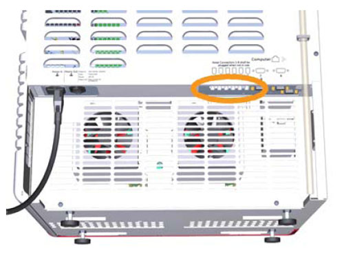
| Possible cause | Suggested remedy |
|---|---|
The network cable is not connected |
Connect the cable, see UNICORN 6.3 Administration and Technical Manual. |
| Possible cause | Suggested remedy |
|---|---|
One or some of the minor modules use too much current. Minor modules include all modules except the Fraction collector, the UV monitor and the pumps. |
The current is cut off by a temperature sensitive component. The instrument can be restarted when the temperature has decreased. If persistent, generate a System error report and contact Service. |
| Possible cause | Suggested remedy |
|---|---|
The instrument is overheated |
Switch off the instrument and wait until the temperature has decreased. Restart the instrument. If this error is recurrent, generate a System error report and contact Service. |
A fuse in the instrument ICU is broken |
Contact Service. |
No electric current in the wall outlet |
Make sure that there is electric current in the wall outlet. |
The power cord is not connected |
Connect the power cord to the wall outlet and to the electrical inlet on the instrument. Make sure that the cord is attached using the clip, thereby preventing the cord from coming loose. |
Conductivity monitor
Issues related to the Conductivity monitor
| Possible cause | Suggested remedy |
|---|---|
Poor mixing function |
Check that the correct Mixer chamber size is used. See Select Mixer chamber, on page 210 for recommendations. To change the Mixer, see Section 7.8.2 Replace the Mixer, on page 366 in the system handbook. |
The column is not equilibrated |
Equilibrate the column. Use the method phase Equilibration. |
The temperature compensation factor is not properly set |
Use a temperature compensation factor. The temperature compensation factor is found in System Control: System Settings:Conductivity. Instruction regarding the factor is also found in Section 7.7.3 Calibrate the Conductivity monitor, on page 354 in the system handbook. |
| Possible cause | Suggested remedy |
|---|---|
The Mixer chamber is too large |
Change to a Mixer chamber with a smaller volume. See Select Mixer chamber, on page 210 for recommendations. To change the Mixer, see Section 7.8.2 Replace the Mixer, on page 366 in the system handbook. |
Bad pump function |
Make sure that the pump operates properly. See Examples of pump pressure curves, on page 427 in the system handbook for example of pump pressure curves. |
Dirt in the tubing |
Make sure that the tubing has been washed properly. |
| Possible cause | Suggested remedy |
|---|---|
Air bubbles are passing through the flow cell |
Check for loose tubing connections. |
A charged particle has been detected |
Prepare the sample so that charged particles are eliminated. |
| Possible cause | Suggested remedy |
|---|---|
Poor mixing function |
Check that the correct Mixer chamber size is used. See Select Mixer chamber, on page 210 for recommendations. To change the Mixer, see Section 7.8.2 Replace the Mixer, on page 366 in the system handbook. |
Air in the flow path |
Purge the pumps. See Section 5.4 Prime inlets and purge pump heads, on page 217 in the system handbook. |
Bad pump function |
Check that the pump is operating properly. See Examples of pump pressure curves, on page 427 in the system handbook for example of pump pressure curves. |
| Possible cause | Suggested remedy |
|---|---|
The Conductivity monitor needs to be calibrated |
Check calibration with a solution with known conductivity. |
The ambient temperature may have decreased/increased |
Use a temperature compensation factor. The temperature compensation factor is found in System Control: System Settings:Conductivity. Instruction regarding the factor is also found in Section 7.7.3 Calibrate the Conductivity monitor, on page 354 in the system handbook. |
Unclean conductivity flow cell |
Clean the Conductivity cell, see Section 7.6.8 Clean the Conductivity flow cell, on page 346 in the system handbook. |
| Possible cause | Suggested remedy |
|---|---|
Poor mixing function |
Check the Mixer chamber size and change chamber if necessary, see Select Mixer chamber, on page 210 in the system handbook. |
Unclean Conductivity flow cell |
Clean the Conductivity flow cell. See Section 7.6.8 Clean the Conductivity flow cell, on page 346 in the system handbook. |
Leaking tubing connections |
Tighten the connectors. If necessary, replace the connectors. |
Air in the Conductivity flow cell |
Use the Flow restrictor. |
| Possible cause | Suggested remedy |
|---|---|
This error can only occur when the temperature compensation is turned on. The error will occur when the temperature is outside the range 2°C to 40°C. |
Make sure the temperature of the calibration solution is within 2°C and 40°C. |
| Possible cause | Suggested remedy |
|---|---|
Solids in the Conductivity flow cell |
Clean the Conductivity cell. See Section 7.6.8 Clean the Conductivity flow cell, on page 346 in the system handbook. |
Air in the Conductivity flow cell |
Flush the Conductivity flow cell with water. |
| Possible cause | Suggested remedy |
|---|---|
Internal errors |
See error log. Restart instrument and retry. If this problem recurs, generate a System error report and contact Service. |
UV monitor U9-M and UV detector unit
Issues related to UV monitor and UV detector unit
| Possible cause | Suggested remedy |
|---|---|
Hardware error |
Switch off the instrument and wait until the temperature has decreased. Restart the instrument. If this error is recurrent, generate a System error report and contact Service. |
Hot surroundings |
Decrease the room temperature. Maximum operating temperature is 35°C. |
The air intake on the rear or on the right side of the instrument is covered |
Make sure that none of the air intakes on the instrument are covered. |
| Possible cause | Suggested remedy |
|---|---|
Large difference in refractive index between buffer A and buffer B |
Due to light spreading effects in the UV cell, the buffer with the highest UV absorption shows the lowest UV absorption in the chromatogram, and the buffer with the lowest UV absorption shows the highest UV absorption. This can occur if there is a large difference in refractive index between buffer A and buffer B and the UV is run at high sensitivity. |
| Possible cause | Suggested remedy |
|---|---|
Poor mixing function |
Check the mixer chamber size and change the chamber if necessary. See Select Mixer chamber, on page 210 in system handbook. |
Bad pump function |
Check that the pump is operating properly. See Select Mixer chamber, on page 210 in system handbook for example of pump pressure curves. |
| Possible cause | Suggested remedy |
|---|---|
Wrong type of UV cell is used |
If a UV cell with 2 mm path length is to be used, use only cells marked U9-2. |
Dirt in the UV flow cell |
Perform a System CIP. See Section 7.6.2 Perform System CIP, on page 325 in system handbook. If necessary, manually clean the UV cell. See Section 7.5.1 Clean the UV flow cell, on page 318 in system handbook. |
Unclean optical fiber connectors |
Clean the connectors. See Section 7.8.4 Replace the UV monitor U9-M flow cell, on page 370 in system handbook. |
Impure buffers |
Check if the signal is noisy with water. |
Air in buffers |
De-gas if necessary. Make sure that both the instrument and the buffers have reached the ambient temperature. |
Air in the UV flow cell |
Use the Flow restrictor. |
Flow restrictor in off-line position |
Use the Flow restrictor. Use the pH valve instruction to manually set the Flow restrictor inline (Flow path:pH valve:Restrictor in-line), or select the Flow restrictor in the Method Settings phase of a method. |
| Possible cause | Suggested remedy |
|---|---|
Dirt in the flow path |
Clean the system in accordance to Section 7.6.2 Perform System CIP, on page 325. Clean the column in accordance to Section 7.6.3 Perform Column CIP, on page 332 in system handbook. |
Dirt in the UV flow cell |
Clean the UV cell. See Section 7.5.1 Clean the UV flow cell, on page 318 in system handbook. |
Air in buffers |
De-gas if necessary. |
Air in the UV flow cell |
Use the Flow restrictor. Use the pH valve instruction to manually set the Flow restrictor inline (Flow path:pH valve:Restrictor in-line), or select the Flow restrictor in the Method Settings phase of a method. |
| Possible cause | Suggested remedy |
|---|---|
The UV flow cell is broken |
Replace the cell. See Section 7.8.4 Replace the UV monitor U9-M flow cell, on page 370 in system handbook. |
UV flow cell is not correctly installed |
Verify that the UV cell is correctly installed. See Section 7.8.4 Replace the UV monitor U9-M flow cell, on page 370 in system handbook. |
No UV flow cell is attached |
Attach UV cell. See Section 7.8.4 Replace the UV monitor U9-M flow cell, on page 370 in system handbook. |
| Possible cause | Suggested remedy |
|---|---|
Unclean optical fiber connectors |
Clean the connectors. See Section 7.8.4 Replace the UV monitor U9-M flow cell, on page 370 in system handbook. |
Wrong wavelength for current buffer |
Change wavelength or buffer |
| Possible cause | Suggested remedy |
|---|---|
Worn-out or broken lamp |
Contact Service |
Dirt on optical sensors in detector |
Remove visible dirt on detector photo diodes. Use lint free lens paper winded around a thin wood splinter (e.g., a match or toothpick). Clean the sensors with Isopropanol through the small hole of the metal plate which covers the sensors. Dry the sensors with clean and dry lint free lens paper. |
Unclean optical fiber connectors |
Clean the connectors. See Section 7.8.4 Replace the UV monitor U9-M flow cell, on page 370 in system handbook. |
The detector is not correctly fitted |
Contact Service |
| Possible cause | Suggested remedy |
|---|---|
Broken UV flow cell |
Replace UV flow cell. See Section 7.8.4 Replace the UV monitor U9-M flow cell, on page 370 in system handbook. |
Unclean optical fiber connectors |
Clean the connectors. See Section 7.8.4 Replace the UV monitor U9-M flow cell, on page 370 in system handbook. |
Dirt in the UV flow cell |
Clean the UV cell. See Section 7.5.1 Clean the UV flow cell, on page 318 in system handbook. |
Wrong wavelength for current buffer |
Change wavelength or buffer |
| Possible cause | Suggested remedy |
|---|---|
Wrong Node ID |
Check the module´s Node ID. If necessary, change the |
The cable between the UV module and the ICU is not connected |
Remove the UV module and make sure that the cable is connected. |
Communication problem |
Contact Service |
Error codes
All modules
| Error code | Description | Action |
|---|---|---|
| 0 - 19 | Internal instrument error | Restart the instrument. If recurrent please contact Service. |
Instrument control unit
| Error code | Description | Action |
|---|---|---|
| 21 - 69 | Internal instrument error | Restart the instrument. If recurrent please contact Service. |
Valve
| Error code | Description | Action |
|---|---|---|
| 20, 22, 24 | Internal instrument error | Restart the instrument. If recurrent please contact Service. |
| 23 | Faulty air sensor | Restart the instrument. If recurrent please contact Service. |
| 25 | High temperature | See Section 8.3 Troubleshooting: Valves on page 414 in the system handbook. |
Pressure monitor
| Error code | Description | Action |
|---|---|---|
| 20, 21, 24-27 | Internal instrument error | Restart the instrument. If recurrent please contact Service. |
| 23 | High temperature | See Pressure monitors, on page 411 in the system handbook. |
Air sensor
| Error code | Description | Action |
|---|---|---|
| 20 | High temperature | See External air sensors, on page 435 in the system handbook. |
Mixer
| Error code | Description | Action |
|---|---|---|
| 25 | Mixer motor error | Restart the instrument. If recurrent please contact Service. |
| 26 | Internal instrument error | Restart the instrument. If recurrent please contact Service. |
| 27 | High temperature | See Mixer, on page 431 in the system handbook. |
pH monitor
| Error code | Description | Action |
|---|---|---|
| 20, 21 | Internal instrument error | Restart the instrument. If recurrent please contact Service. |
| 25 | No factory calibration | Contact Service |
| 26 | High temperature | See pH monitor and pH valve, on page409 in the system handbook. |
Conductivity monitor
| Error code | Description | Action |
|---|---|---|
| 20-27 | Internal instrument error | Restart the instrument. If recurrent please contact Service. |
| 28 | High temperature | See Conductivity monitor, on page 405 in the system handbook. |
| 29 | Temperature data error | Restart the instrument. If recurrent please contact Service. |
| 32-34 | No factory calibration | Contact Service |
Pump
| Error code | Description | Action |
|---|---|---|
| 51-53 | Mixer motor error | Restart the instrument. If recurrent please contact Service. |
| 54 | Internal instrument error | See Section 8.5 Troubleshooting: Pumps, on page 424 in the system handbook. |
UV monitor U9-M
| Error code | Description | Action |
| 21, 25, 26, 31 | Grating error | Restart the instrument. If recurrent please contact Service. |
| 22, 23, 32 | Block filter error | Restart the instrument. If recurrent please contact Service. |
| 24 | Internal instrument error | Restart the instrument. If recurrent please contact Service. |
| 27 | Spectrum calibration error | Restart the instrument. If recurrent please contact Service. |
| 28, 29 | Lamp error | Restart the instrument. If recurrent please contact Service. |
| 30 | High temperature | See UV monitor U9-M and UV detector unit, on page 398 in the system handbook. |
UV detector U9-D
| Error code | Description | Action |
|---|---|---|
| 24, 26, 28, 29, 31, 33 | Internal instrument error | Restart the instrument. If recurrent please contact Service. |
| 25 | Too low light intensity | Check that the detector and flow cell are fitted correctly. If warning reappears, contact Service. |
| 27 | Too high light intensity | Check that the detector and flow cell are fitted correctly. If warning reappears, contact Service. |
| 30 | Too high light intensity, R channel. | Check that the detector is fitted correctly. If warning reappears, contact Service. |
| 32 | Too high S light intensity, S channel. | Check that the flow cell is fitted correctly. If warning reappears, contact Service. |
| 34 | No light detected | Check optical pathway and restart the instrument. If recurrent please contact Service. |
| 35 | Too low light intensity, R channel. | Check that the detector is fitted correctly. If warning reappears, contact Service. |
| 36 | Too low light intensity, S channel. | No light through flow cell. Check solution absorption and that the cell is fitted correctly. |
UV monitor U9-L
| Error code | Description | Action |
| 51 | High temperature | See UV monitor U9-L, on page 403 in the system handbook. |
| 52, 55 | Low lamp intensity | Contact Service |
| 54 | Autozero out of range | Autozero requested when AU value is larger than 2. |
| 58 | Too low light intensity, S channel. | No light through flow cell. Check solution absorption and that the cell is fitted correctly. |
| 59, 60 | Internal instrument error | Restart the instrument. If recurrent please contact Service. |
| 61 | Measurement error | Restart the instrument. If recurrent please contact Service. |
Fraction collector F9-R
| Error code | Description | Action |
|---|---|---|
| 20 | High temperature | See Section 8.4 Troubleshooting: Fraction collector, on page 422 in the system handbook. |
| 21 | Drop sync warning | Clean the sensor and remove air bubbles in the flow path. |
| 22 | Tube sensor error | Check that the tube sensor is adjusted properly. |
| 23 | Delay queue full | Increase the fraction size. Fraction size must be greater than 1/10 of the delay volume. |
| 24, 26 | Internal instrument error | Restart the instrument. If recurrent please contact Service. |
| 25, 28 | Too fast tube change | Increase the fraction size or lower the flow rate. |
| 27 | Drop sync error | Clean the drop sensor |
Instrument control panel
| Error code | Description | Action |
|---|---|---|
| 51 | High temperature | See Instrument control panel, on page 437 in the system handbook. |
I/O-box
| Error code | Description | Action |
|---|---|---|
| 20 | High temperature | See section "Troubleshooting" |
| 21 | Analog in signal below -2V | Check the external equipment connected to the I/O-box. |
| 22 | Analog in signal above 2V | Check the external equipment connected to the I/O-box. |
| 23-28 | Internal instrument error | Restart the instrument. If recurrent please contact Service. |
External air sensors
Issues related to External air sensors
| Possible cause | Suggested remedy |
|---|---|
Hardware error |
Switch off the instrument and wait until the temperature has decreased. Restart the instrument. If this error is recurrent, generate a System error report and contact Service. |
Hot surroundings |
Decrease the room temperature. Maximum operating temperature is 35°C. |
| Possible cause | Suggested remedy |
|---|---|
One of the connections is not tight enough |
Tighten the connectors. |
| Possible cause | Suggested remedy |
|---|---|
One of the connections is not tight enough |
Tighten the connectors. |
| Possible cause | Suggested remedy |
|---|---|
The external air sensor has not been selected in UNICORN |
Select the external air sensor in UNICORN. Refer to the installation instructions delivered together with the external air sensor. |
The cable between the external air sensor and the ICU is not connected |
Check the back of the instrument and make sure that the cable is connected. |
pH valve
Issues related to pH valve
| Possible cause | Suggested remedy |
|---|---|
The dummy electrode was dry when it was installed in the valve. |
1 Remove the dummy electrode. |
Maintenance
Maintenance instructions and procedures.
ÄKTA pure - periodic maintenance program
This section lists the periodic maintenance activities that should be performed by the ÄKTA pure users, as well as maintenance activities that should be performed when required.

Hazardous biological agents during run. When using hazardous biological agents, run System CIP and Column CIP to flush the entire system tubing with bacteriostatic solution (e.g., NaOH) followed by a neutral buffer and finally distilled water, before service and maintenance.

Hazardous chemicals during run. When using hazardous chemicals, run System CIP and Column CIP to flush the entire system tubing with distilled water, before service and maintenance.
Always use appropriate personal protective equipment during operation and maintenance.
Maintenance operations should be performed by the user at regular intervals
The detailed procedures can be found in the ÄKTA pure System Handbook located in the related documents tab.
| Maintenance | See section in ÄKTA pure System Handbook |
|---|---|
| Calibrate the pH monitor | See section 7.7.1 Calibrate the pH monitor. |
The following periodic maintenance should be performed by the user of ÄKTA pure weekly.
| Maintenance | See section in ÄKTA pure System handbook |
|---|---|
| Calibrate pressure monitors | Section 7.7.2 Calibrate the pressure monitors |
Change pump rinsing solution
The detailed procedures can be found in the ÄKTA pure System Handbook located in the related documents tab.
| Maintenance | See section in ÄKTA pure System handbook |
|---|---|
| Change pump rinsing solution | Section 7.3.1 Change pump rinsing solution |
The following periodic maintenance should be performed by the user of ÄKTA pure, monthly.
| Maintenance | See section in the ÄKTA pure System Handbook |
|---|---|
| Check the Flow restrictor | Section 7.4.1 Check the Flow restrictor |
The following periodic maintenance should be performed by the user of ÄKTA pure, bi-annually.
| Maintenance | See section in the ÄKTA pure System Handbook |
|---|---|
| Clean the UV flow cell | Section 7.5.1 Clean the UV flow cell |
Replace pH electrode
The following periodic maintenance should be performed by the user of ÄKTA pure, bi-annually.
| Maintenance | See section in the ÄKTA pure System Handbook |
|---|---|
| Replace pH electrode | Section 7.5.2 Replace the pH electrode |
| Maintenance action | See section in the ÄKTA pure System Handbook |
|---|---|
| Clean the instrument externally | Section 7.6.1 Clean the instrument externally |
| Perform System CIP | Section 7.6.2 Perform System CIP |
| Perform Column CIP | Section 7.6.3 Perform Column CIP |
| Clean the Fraction collector F9-R | Section 7.6.4 Clean the Fraction collector |
| Replace tubing and connectors | Section 7.8.1 Replace tubing and connectors |
| Storage of pH electrode | Section 7.6.5 Storage of the pH electrode |
| Clean the pH electrode | Section 7.6.6 Clean the pH electrode |
| Clean the Conductivity flow cell | Section 7.6.8 Clean the Conductivity flow cell |
| Calibrate the Conductivity monitor | Section 7.7.3 Calibrate the Conductivity monitor |
| Calibrate the UV monitor | Section 7.7.4 Calibrate the UV monitors |
| Replace Mixer | Section 7.8.2 Replace the Mixer |
| Replace inline filter | Section7.3.2 Replace the inline filter |
| Replace O-ring in Mixer | Section 7.8.3 Replace the O-ring of the Mixer |
| Replace UV flow cell | Section 7.8.4 Replace the UV monitor U9-M flow cell |
| Replace the Flow restrictor | Section 7.8.6 Replace the Flow restrictor |
| Replace inlet filters | Section 7.8.7 Replace the inlet filters |
| Clean the check valves | Section 7.6.7 Clean the pump head check valves |
| Replace check valves | Section 7.8.8 Replace the pump head check valves |
| Replace pump piston seals | Section 7.8.9 Replace pump piston seals of Pump P9 |
| Replace pump pistons | Section 7.8.10 Replace pump pistons |
| Replace pump rinsing system tubing |
Section 7.8.11 Replace pump rinsing system tubing |